Novel neck exercising instrument
An exerciser and neck technology, which is applied in the field of new neck exerciser, can solve the problems of heavy structure, poor flexibility, rigid exercise movements, etc., and achieve the effect of strong flexibility, avoiding waste of time, and compact structure
- Summary
- Abstract
- Description
- Claims
- Application Information
AI Technical Summary
Problems solved by technology
Method used
Image
Examples
Embodiment 1
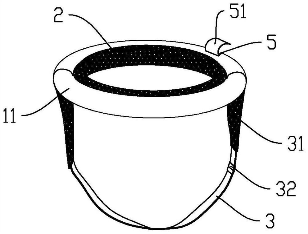
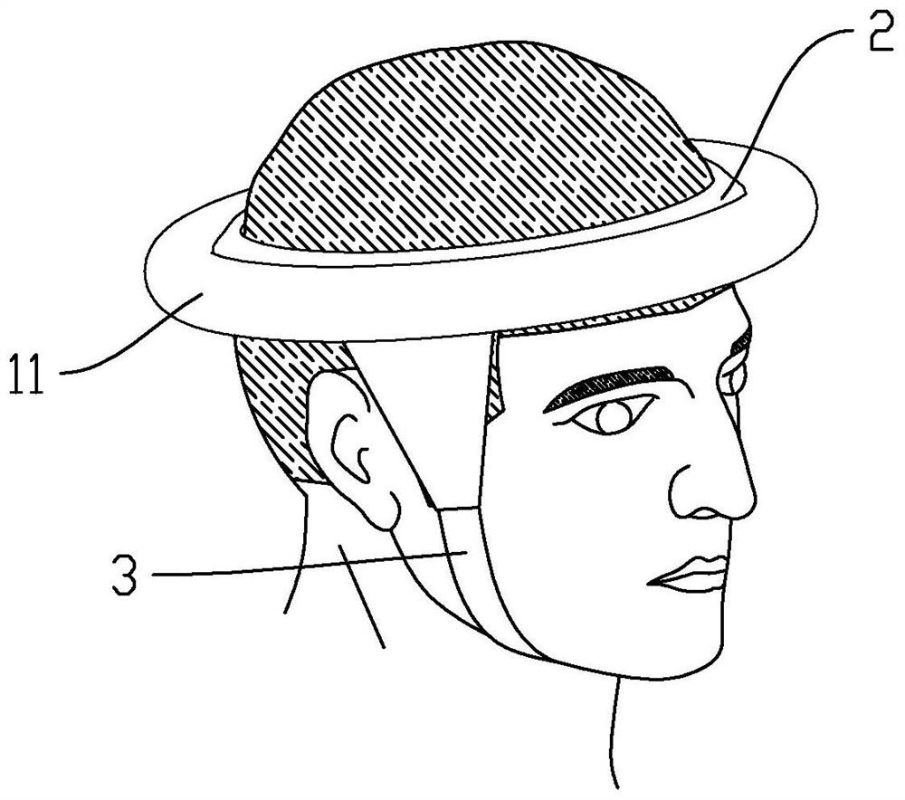
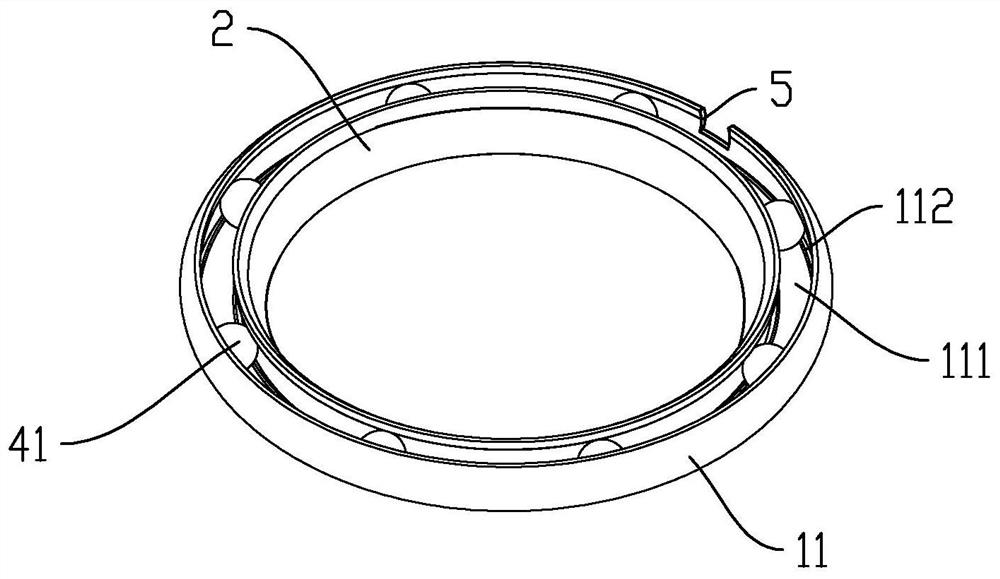
[0055] see Figure 3 to Figure 5 , combined with figure 1 and figure 2 , this embodiment discloses a new type of neck exercise apparatus, which includes a first body 11 , an inner lining 2 , a fixing belt 3 and a first weight 41 .
[0056] Wherein, the first main body 11 is an annular tubular structure, which is used to be sleeved on the top of the head (such as figure 2 As shown), the first main body 11 mainly plays a load-bearing role. The first main body 11 in this embodiment has an integrated structure. In other embodiments, the first main body 11 can adopt two or more semicircular cross-sections. The shell is assembled. Specifically, such as image 3 , Figure 5 As shown, the inside of the first body 11 has a first cavity 111, and four centrally symmetrical flange structures are arranged in the first cavity 111, and the flange structures surround the inner wall of the first cavity 111 in a ring shape. structure, each of the flange structures together constitutes t...
Embodiment 2
[0062] see Figure 6 , The difference between this embodiment and Embodiment 1 lies in the difference in the internal rail structure of the main body and the connection mode of the load-carrying parts. The same parts as in Embodiment 1 will not be described again. The main body 1 in this embodiment adopts the second main body 12. The second main body 12 is an annular tubular structure with a second cavity 121 inside it. The second cavity 121 is provided with an annular second track 122 arranged along the second cavity 121. The second track 122 has a second track cavity 123 in the shape of a "mountain" inside, and the outer end of the second track 122 is movably connected with a second A moving part 71, specifically, the first moving part 71 includes a base 711 connected to each other, a connecting rod 712 and a guide wheel 713, the base 711 is located outside the first track 122, and the connecting rod 712 is inserted into the second track cavity 123 , the guide wheel 713 is ...
Embodiment 3
[0065] combine Figure 7 and Figure 8 The difference between the present embodiment and the first embodiment lies in the different structure of the main body and the different connection method of the load-carrying parts. The same parts as in Embodiment 1 will not be repeated. The main body 1 in this embodiment is the third main body 13, and the third main body 13 is a ring-shaped plate structure. The outer surface of the third main body 13 is provided with a ring-shaped third body. Three tracks 131 , the third track 131 is movably connected with the second moving part 72 through a concave-convex locking structure, and the second moving part 72 can move along the third track 131 .
[0066] The second moving part 72 is connected with a third loading part 43. Specifically, the outer end of the second moving part 72 is made of a magnetic metal material, and the third loading part 43 is magnetically attracted to the second moving part 72. Made of magnetic material, the third lo...
PUM
 Abstract
Description
Claims
Application Information
 - R&D
- Intellectual Property
- Life Sciences
- Materials
- Tech Scout
- Unparalleled Data Quality
- Higher Quality Content
- 60% Fewer Hallucinations
Browse by: Latest US Patents, China's latest patents, Technical Efficacy Thesaurus, Application Domain, Technology Topic, Popular Technical Reports.
© 2025 PatSnap. All rights reserved.Legal|Privacy policy|Modern Slavery Act Transparency Statement|Sitemap|About US| Contact US: help@patsnap.com


