Traction device of flat knitting machine

A technology of a pulling device and a flat knitting machine, which is applied in knitting, weft knitting, textiles and papermaking, etc., and can solve problems such as good pulling effect, poor pulling effect, inability to realize fabric segmentation, layered pulling, etc. problems, to achieve a good pulling effect and avoid damage to the fabric

Inactive Publication Date: 2021-10-19
胡彦刚
View PDF0 Cites 0 Cited by
  • Summary
  • Abstract
  • Description
  • Claims
  • Application Information

AI Technical Summary

Problems solved by technology

[0003] The present invention overcomes the deficiency that the existing roller devices on the knitting machine can only pull at the same time, cannot realize segmented and layered pulling of the fabric, resulting in poor pulling effect, and provides a pulling device for flat knitting machines , it can realize the segmented and layered pulling of the fabric, and the pulling effect is good

Method used


Image

  • Traction device of flat knitting machine
  • Traction device of flat knitting machine
  • Traction device of flat knitting machine

Examples


Embodiment 1

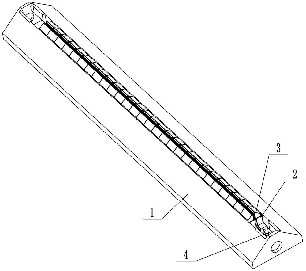
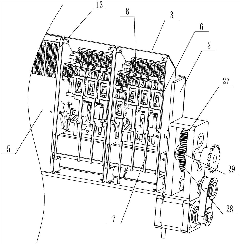
[0039] Embodiment 1: A kind of drawing device of flat knitting machine (see attached figure 1 To attach Figure 5 ), including a frame 1, a mounting frame 2, a drive assembly, and several pulling mechanisms 3 installed on the mounting frame at intervals. Two oppositely arranged mounting frames are installed, and a row of pulling mechanisms are installed on the mounting frames, the pulling mechanisms are arranged oppositely, and the fabric is pulled between the two oppositely arranged pulling mechanisms. The pulling mechanism includes an installation box 5 and several pulling units installed on the installation box. The pulling unit includes a lifting seat 6 that can be lifted and installed in the installation box, and an opening and closing rod 7 hinged on the lifting seat. The pulling rake 8 is installed, and the pulling rake can stretch out the installation box, and the lifting drive block 9 for driving the lifting seat to move and the deflection dial 10 for driving the ope...

Embodiment 2

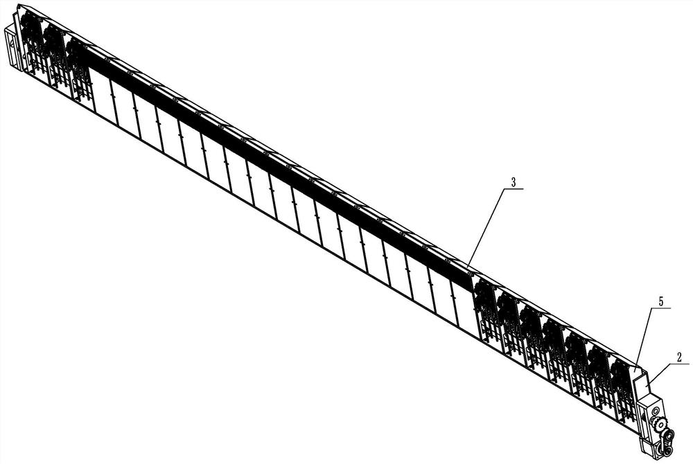
[0047] Embodiment 2: A kind of drawing device of flat knitting machine (see attached Figure 6 ), its structure and principle can be similar to any one of Embodiments 1, 3, 4, 5, and 7 of the present application. The main difference is that the drive assembly in this embodiment includes a drive shaft and several drive shafts. On the transmission shaft, a drive shaft is installed in the installation box, and the lifting drive block and the deflection dial block are all arranged on the drive shaft; the lifting seat is provided with a rack 30, and the lifting drive block is provided with a section of arc-shaped meshing teeth 31, The meshing gear fits with the rack, the drive shaft rotates to drive the gear rack to move upward, the drive shaft rotates to make the deflection shift block touch the opening and closing rod, and the pulling rake at the upper end of the opening and closing rod retracts from the outside of the installation box to the inside .

Embodiment 3

[0048] Embodiment 3: A kind of pulling device of flat knitting machine (see attached Figure 7 ), its structure and principle can be similar to any other embodiment of the present application, the main difference is that in this embodiment, a rest motor 37 for driving the rest part to rotate is installed on the mounting bracket and the rest part one by one, and the rest part rotates It is installed in the installation box, and the rest part rotates eccentrically. One end of the rest part is provided with a worm gear 38, and the output shaft of the rest motor is connected with a worm screw 39, and the worm screw is connected with the worm gear drive.


PUM


Abstract

The invention discloses a traction device of a flat knitting machine, and aims to overcome the defect that the traction effect is poor due to the fact that a roller device on an existing knitting machine can only conduct traction at the same time and cannot conduct segmented and layered traction on fabric. The traction device comprises a rack, an installation frame, a driving assembly and a traction mechanism installed on the installation frame, a guide groove is formed in the rack, the installation frame is installed in the guide groove, the traction mechanism comprises an installation box and a plurality of traction units installed on the installation box, each traction unit comprises a lifting seat installed in the installation box in a lifting mode and an opening and closing rod hinged to each lifting seat, a traction rake is installed on each opening and closing rod and can extend out of the installation box, and a lifting driving block used for driving each lifting seat to move and a deflection shifting block used for driving each opening and closing rod to rotate are installed on the driving assembly. The traction device of the flat knitting machine can realize segmented and layered traction of fabrics, and is good in traction effect.

Description

technical field [0001] The invention relates to the technical field of flat knitting machines, more specifically, it relates to a pulling device for flat knitting machines. Background technique [0002] At present, most of the pulling devices of knitting machines use roller devices, which are easy to realize the pulling action and the cost is relatively low. However, the roller device is aimed at pulling the whole fabric at the same time, and cannot realize the segmented and layered pulling of the fabric. , especially in the fully formed machine, there are great limitations, and the rubber layer in the roller has a certain loss, and the fabric will be easily deformed and damaged when pulled to a certain extent, which increases the scrap rate. Contents of the invention [0003] The present invention overcomes the deficiency that the existing roller devices on the knitting machine can only pull at the same time, cannot realize segmented and layered pulling of the fabric, res...

Claims


Application Information

Patent Timeline
Patent Type & Authority Applications(China)
IPC IPC(8): D04B15/90
CPCD04B15/90
Inventor 胡彦刚
Owner 胡彦刚
Why Eureka
Try Eureka