Spherical turntable monitoring camera with panoramic monitoring function

A monitoring camera and panoramic monitoring technology, which is applied in the direction of image communication, color TV parts, TV system parts, etc., can solve the problems of weak anti-dust ingress function of the protective shell, reduce the monitoring clarity of the monitoring probe, etc., and achieve the guarantee Monitor the effect of clarity

Active Publication Date: 2021-10-19
重庆都宸工业技术有限公司
View PDF5 Cites 3 Cited by
  • Summary
  • Abstract
  • Description
  • Claims
  • Application Information

AI Technical Summary

Problems solved by technology

[0004] However, the technical solution provided by this patent has a weak anti-dust function for the protective case. When the camera encounters haze or sandy weather, the dust in the air is easily blown in by the wind through the gap between the disassembled case and the protective case. Dismantling the shell will cause technical problems that reduce the monitoring clarity of the monitoring probe

Method used


Image

  • Spherical turntable monitoring camera with panoramic monitoring function
  • Spherical turntable monitoring camera with panoramic monitoring function
  • Spherical turntable monitoring camera with panoramic monitoring function

Examples


Embodiment 1

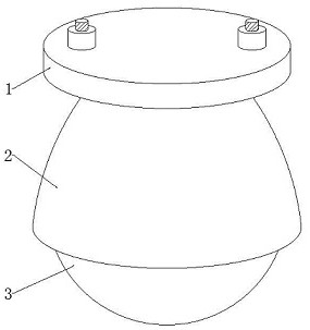
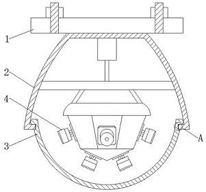
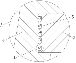
[0038] see Figure 1-4 , Figure 6-7 , in an embodiment of the present invention, a spherical turntable monitoring camera for panoramic monitoring, including a top plate 1, a protective case 2, a dismantling case 3 and a monitoring probe 4, the internal position of the inner wall at the bottom of the protective case 2 is equal to the vertical direction. A number of anti-dust components 5 that can prevent continuous ingress of dust are embedded in the column;

[0039] Each group of anti-ash components 5 includes an inner shell 501, an ash control component 502 that can control the ingress and egress of dust, an outer shell 503, a material control component 504 that can control the ingress and egress of dust-absorbing materials, and an ash-retaining component 505 that can isolate dust.

[0040] In the embodiment of the present invention, the appearance of each inner shell 501 is in the shape of a number 6 with a hollow interior, an upper left opening, a flat top and an inclinat...

Embodiment 2

[0044] see Figure 4 Compared with Embodiment 1, this embodiment of the present invention differs in that each group of ash control components 502 includes a rotating shaft 5021 and a folding plate 5022 .

[0045] In the embodiment of the present invention, each rotating shaft 5021 is rotatably installed in the center between the front and rear inner walls of each inner shell 501 in the front and rear horizontal directions. The appearance of the boards 5022 is in the shape of a left-down oblique and right-horizontal bending shape in a longitudinal section, and the inner bending angle of each folding board 5022 is 120°, and each folding board 5022 is in a static equilibrium state under normal conditions, and each The right ends of each flap 5022 are magnetic;

[0046] The appearance of the folded plate 5022 here is set as a bent shape with a downward slope to the left and a horizontal right on a longitudinal section, so that the dust can directly fall to the surface of the lef...

Embodiment 3

[0049] see Figure 4-7 Compared with Embodiment 1, this embodiment of the present invention differs in that each group of material control components 504 includes a baffle 5041 , a material storage tank 5042 and clear water 5043 .

[0050] In the embodiment of the present invention, the upper end of the right inner wall of each housing 503 is fixedly installed with a limiting plate 5031 in a horizontal direction, and the position directly above each limiting plate 5031 is slidingly installed on the right inner wall of each housing 503. The baffle plate 5041, the length of each limiting plate 5031 is less than the length of each baffle plate 5041, and the position between the upper end of the right outer wall of each inner shell 501 and the upper end of the right inner wall of each outer shell 503 is fixedly equipped with a storage tank 5042, the inner position of each material storage tank 5042 is all preloaded with clear water 5043.

[0051] In the embodiment of the present ...


PUM


Abstract

The invention provides a panoramic monitoring spherical rotary table monitoring camera, and the camera comprises a mounting top plate, a protective shell, a detachable shell and a monitoring probe; a plurality of dust entering prevention assemblies capable of preventing dust from continuously entering are embedded in the inner wall of the bottom end of the protective shell in an up-down vertical direction in equal rows; each group of dust entering prevention assembly comprises an inner shell, a dust control assembly capable of controlling dust to enter and exit, an outer shell, a material control assembly capable of controlling dust suction materials to enter and exit, and a dust isolation assembly capable of isolating dust. According to the panoramic monitoring spherical rotary table monitoring camera, the dust prevention function of the protective shell can be improved, dust in the air is not prone to being blown into the detachable shell through a gap between the detachable shell and the protective shell even if the camera encounters haze or sand and dust weather, and the monitoring definition of the monitoring probe is guaranteed.

Description

technical field [0001] The invention relates to the technical field of monitoring, and more specifically relates to a spherical turntable monitoring camera for panoramic monitoring. Background technique [0002] The existing panoramic spherical cameras often work for 24 hours for a long time when monitoring, which makes the installation environment of the panoramic camera more demanding. Maintenance and maintenance are carried out inside, but most of the existing panoramic cameras are integrated equipment, which cannot be disassembled at will, and it is very troublesome to disassemble during maintenance. [0003] In view of the above problems, regarding the technical problem that the panoramic camera is inconvenient to disassemble, after a large number of searches, a kind of intelligent panoramic dome surveillance camera with the patent number CN201920961297.6 was inquired, including the installation of the top plate, and the bottom of the installation top plate is fixedly c...

Claims


Application Information

Patent Timeline
Patent Type & Authority Applications(China)
IPC IPC(8): H04N5/225H04N5/232
CPCH04N23/50H04N23/698
Inventor 何建中袁楚才谭赛郭永胜万晨
Owner 重庆都宸工业技术有限公司
Why Eureka
Try Eureka