Endoscope switching structure, mounting jig, adapter, switching device, mounting method and surgical robot
An adapter and laparoscope technology, which is applied in the field of medical devices, can solve the problems of compatibility between the robot arm and the laparoscope and the difficulty in finding the zero position, and achieve the effect of solving compatibility difficulties and good adaptability
- Summary
- Abstract
- Description
- Claims
- Application Information
AI Technical Summary
Problems solved by technology
Method used
Image

Examples
Example Embodiment
[0092] Example one
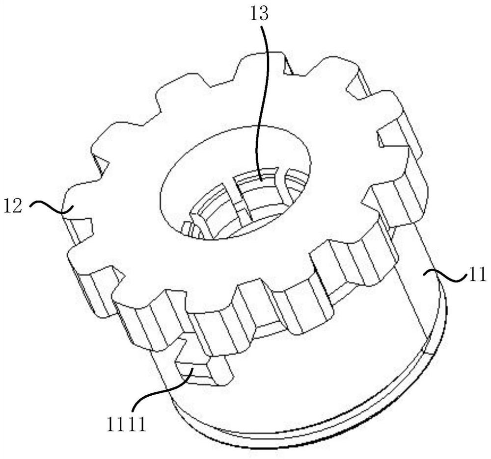
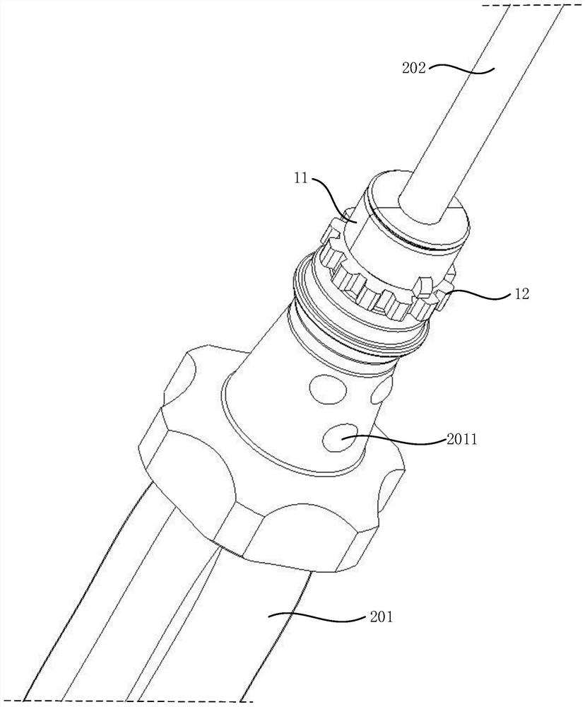
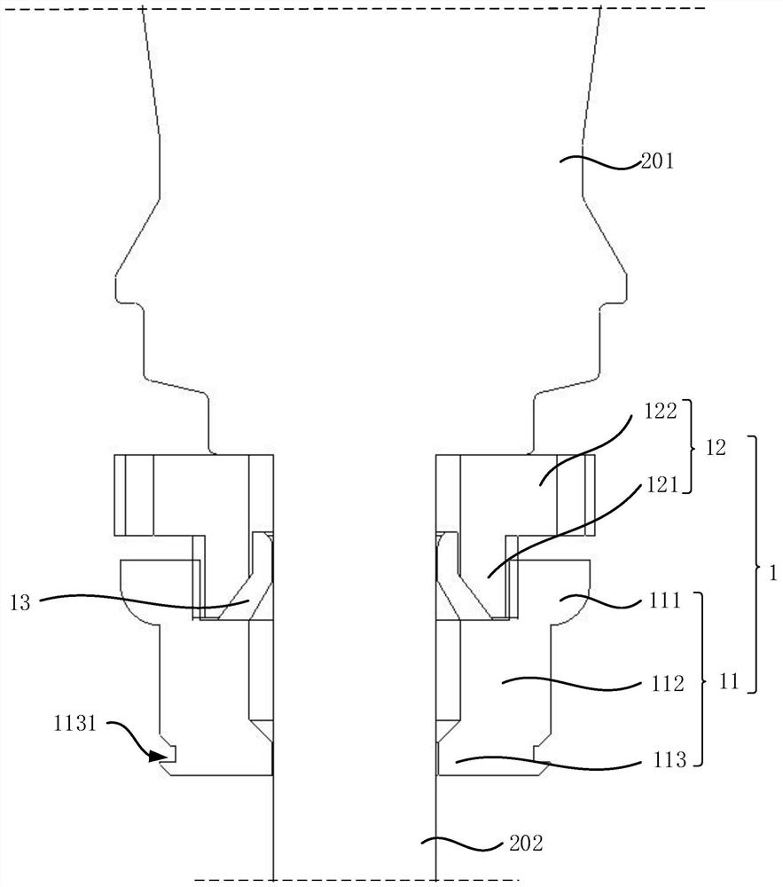
[0093] This embodiment provides a cavoscope adapter structure 1, which is capable of fixing a cavoscope to facilitate fixing the cavity in need, where the "required position" can be based on the cavus Actual use condition adjustment. like figure 1 with figure 2 As shown, the cavus adapter structure 1 includes a fixed ring 11, a lock ring 12, and a clamping portion 13. The fixing ring 11 and the lock ring 12 can be arranged outside the insertion portion 202 of the cavus, and the fixed ring 11 and the lock ring 12 are active. Any one of the fixed ring 11 and the lock ring 12 is provided with at least two clamping portions 13, at least two holding portions 13 can clamp the insertion portion at the fixed ring 11 and the lock ring 12. 202, thereby securing the cavoscope adapter 1 with the cavoscope.
[0094] The cavus generally includes the handle 201 and the insertion portion 202. In a cavus of different types or brands, the size, shape, and the length of the inse...
Example Embodiment
[0113] Example 2
[0114] like Figure 4 As shown, the present embodiment provides a cavoscope adapter structure 1, which is different from the embodiment of the first embodiment in that the configuration of the lock ring drive the clamping portion 13 is different.
[0115] like Figure 5 with Image 6 As shown, the lock ring 12 is set in the fixed ring 11 and threaded with the fixed ring 11, and the holding portion 13 is extended along the axial direction of the fixed ring 11 along the axial direction of the fixing ring 11, and is provided on the holding portion 13. The flange 131 extending in the circumferential direction of the ring 11 is provided with a circular arc-shaped hole 1311, and the width of the circular arc hole 1311 gradually decreases along the locking direction of the fixed ring 11 and the lock ring 12, and locks the ring. 12 is provided with a first locking pin 123 that can be slid along the circular arc hole 1311.
[0116] When the lock ring 12 is threaded with the...
Example Embodiment
[0120] Example three
[0121] like Figure 8 As shown, the present embodiment provides a cavoscope adapter structure 1, which differs from the second embodiment one and the first examples of the second embodiment in the configuration of the locking ring drive holding portion 13.
[0122] like Figure 9 As shown, the holding portion 13 extends along the axial direction of the lock ring 12 along the locking ring 12, and a spiral extending lock groove 132 is provided on the holding portion 13, and the depth of the locking groove 132 gradually decreases in the helix direction. Small, the depth of the lock groove 132 is provided with a card casing groove 1321; the fixing ring 11 is sleeved outside the lock ring 12, and the inner wall of the fixed ring 11 has a second locking pin 114, the second The locking pin 114 can slide along the locked groove 132 and can be cardd within the latch groove 1321.
[0123] In this embodiment, the fixing ring 11 and the lock ring 12 achieve a spiral conne...
PUM
 Abstract
Description
Claims
Application Information
 - R&D Engineer
- R&D Manager
- IP Professional
- Industry Leading Data Capabilities
- Powerful AI technology
- Patent DNA Extraction
Browse by: Latest US Patents, China's latest patents, Technical Efficacy Thesaurus, Application Domain, Technology Topic.
© 2024 PatSnap. All rights reserved.Legal|Privacy policy|Modern Slavery Act Transparency Statement|Sitemap