Multiband irradiation physiotherapy instrument
A physiotherapy instrument and multi-band technology, applied in the field of phototherapy, can solve the problems of small side effects, waste of medical resources, reduce the treatment effect of phototherapy lamps, etc., and achieve the effect of convenient movement
- Summary
- Abstract
- Description
- Claims
- Application Information
AI Technical Summary
Problems solved by technology
Method used
Image
Examples
Embodiment 1
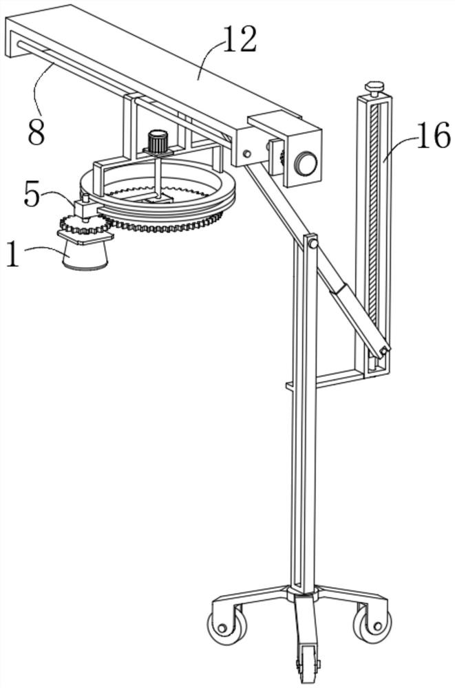
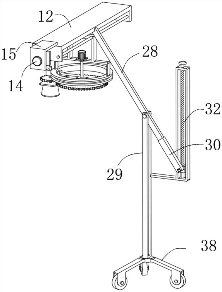
[0027] see figure 1 , figure 2 , Figure 4 and Figure 7 , a physiotherapy instrument for multi-band irradiation in the illustration, including a phototherapy lamp 1, a plurality of lamp holders 2 are arranged inside the phototherapy lamp 1, and the lamp holders 2 are arranged in a ring, and the bottom of the phototherapy lamp 1 is provided with lamp holders 2 a plurality of U-shaped irradiation areas 3 corresponding to the positions, the top of the phototherapy lamp 1 is fixed with a fixed plate 4, and the fixed plate 4 is provided with a rotating member 5 for rotating the phototherapy lamp 1, and the rotating member 5 A disc 6 is slidably connected to an end away from the fixed plate 4 , and a connecting frame 7 is fixed between two ends of the disc 6 , and a moving device 8 for adjusting the overall position of the disc 6 is provided on the connecting frame 7 .
[0028] Wherein, the moving device 8 includes a moving plate 9, the two ends of the moving plate 9 are fixedl...
Embodiment 2
[0033] see Figure 5 with Image 6 , the present embodiment further explains the embodiment 1, the disc 6 is provided with an annular chute 17, the annular chute 17 is slidably connected with a slider 18, and the slider 18 is rotatably connected with the rotating member 5, One end of the slider 18 is fixed with a connecting rod 19, the connecting rod 19 is fixed with a rotating rod 20, and the end of the rotating rod 20 away from the connecting rod 19 is fixed with a second motor 21, and the second motor 21 is set On the connecting frame 7.
[0034] Wherein, the rotating member 5 includes a rotating shaft 22, and one end of the rotating shaft 22 passes through the slider 18 and is fixedly connected between the fixed plate 4, and a first bearing connecting member 23 is arranged between the rotating shaft 22 and the slider 18, and the The bearing on the rotating shaft 22 is connected with a rolling gear 24;
[0035] Simultaneously, the rolling gear 24 is meshed with a gear plat...
Embodiment 3
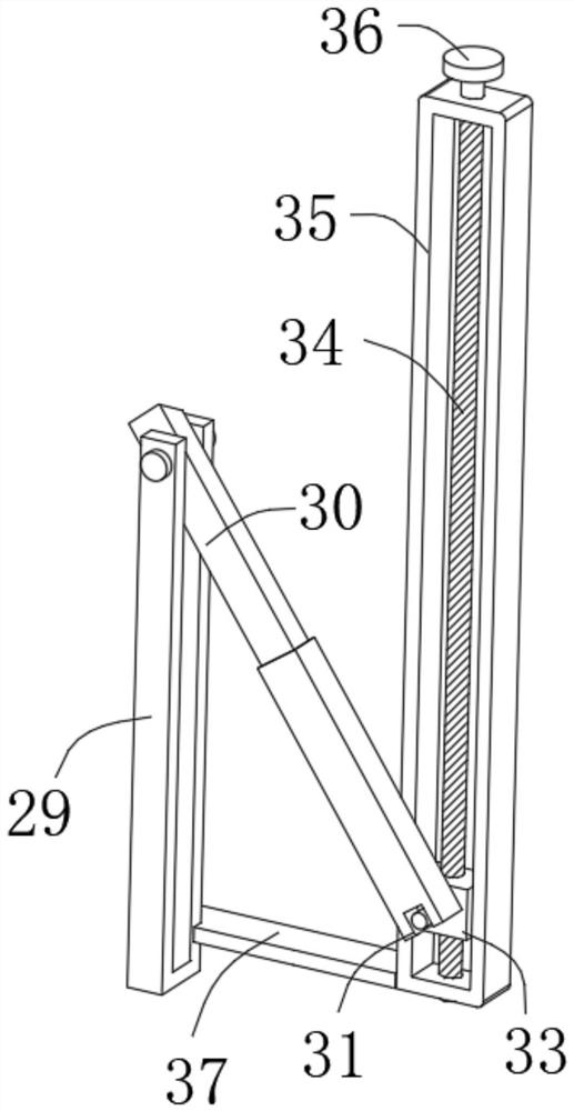
[0038] see image 3 , this embodiment further illustrates Example 1, the adjustment member 16 includes a connecting plate 28, one end of the connecting plate 28 is fixedly connected to the concave frame 12, and the end far away from the concave frame 12 is connected to a support through a connecting shaft for rotation. frame 29, the end of the connecting plate 28 away from the concave frame 12 is fixed with a telescopic plate 30, the end of the telescopic plate 30 away from the connecting plate 28 is rotatably connected with a short shaft 31, and the short shaft 31 is provided with a moving part 32 .
[0039] Wherein, the moving part 32 includes a moving block 33, which is fixedly connected with the short shaft 31, and the inner thread of the moving block 33 is connected with a second screw rod 34, and the side walls of the moving block 33 slide together Connected with a rectangular frame 35, one end of the second screw mandrel 34 passes through the rectangular frame 35 and i...
PUM
 Abstract
Description
Claims
Application Information
 - R&D
- Intellectual Property
- Life Sciences
- Materials
- Tech Scout
- Unparalleled Data Quality
- Higher Quality Content
- 60% Fewer Hallucinations
Browse by: Latest US Patents, China's latest patents, Technical Efficacy Thesaurus, Application Domain, Technology Topic, Popular Technical Reports.
© 2025 PatSnap. All rights reserved.Legal|Privacy policy|Modern Slavery Act Transparency Statement|Sitemap|About US| Contact US: help@patsnap.com


