Chemical raw material stirring device

A stirring device and a technology for chemical raw materials, which are applied to mixers with rotating stirring devices, chemical instruments and methods, and dissolution, etc., can solve the problems of low stirring efficiency and single means, achieve sufficient stirring, increase stirring intensity, and avoid The effect of entering the inside of the stirring fan blade

Inactive Publication Date: 2021-10-22
李桂春
View PDF0 Cites 1 Cited by
  • Summary
  • Abstract
  • Description
  • Claims
  • Application Information

AI Technical Summary

Problems solved by technology

[0005] Aiming at the deficiencies of the prior art, the present invention provides a chemical raw material stirring device, which solves the problem that the existing chemical raw material stirring device has a single means of stirring and low stirring efficiency, and can prevent particles from sinking to the bottom during the stirring process. Make the mixing of chemical raw materials more fully

Method used


Image

  • Chemical raw material stirring device
  • Chemical raw material stirring device
  • Chemical raw material stirring device

Examples


Embodiment 1

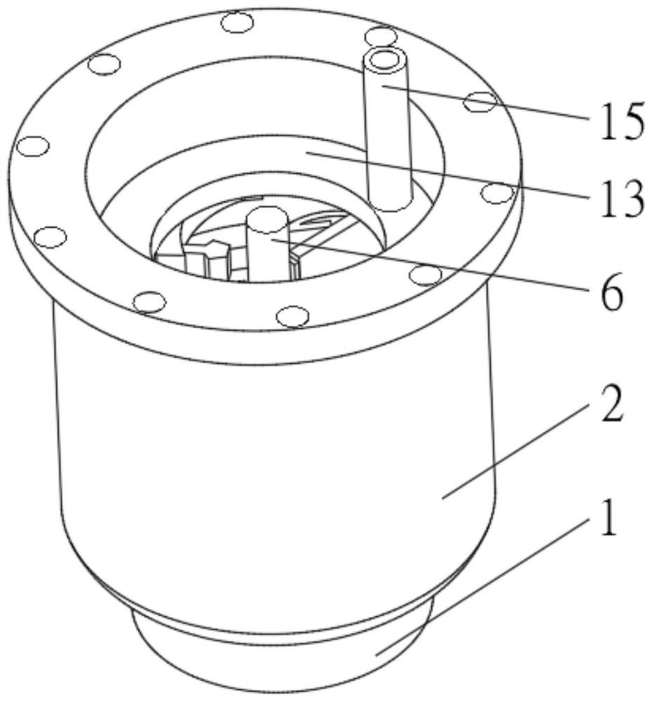
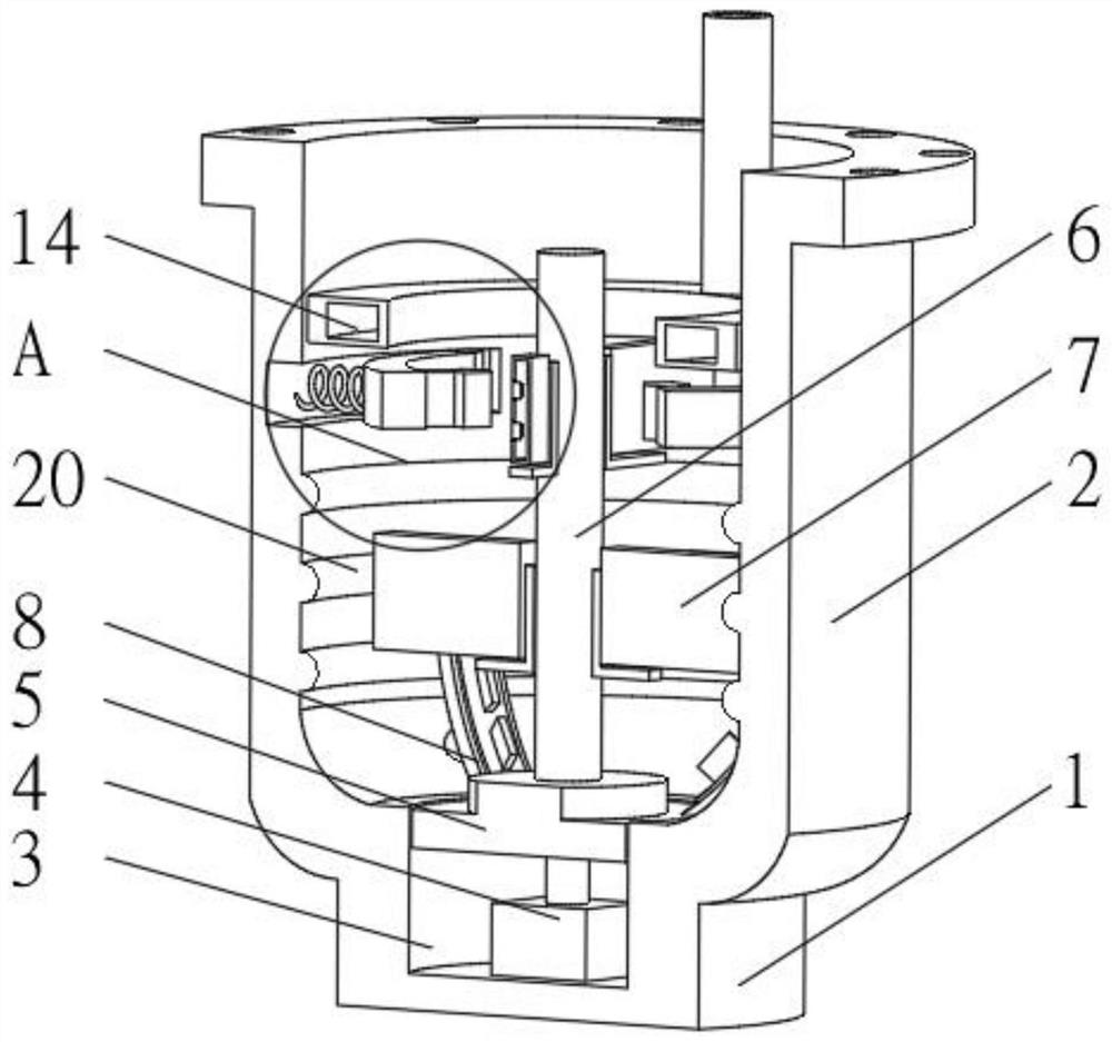
[0029] see Figure 1-2 , the present invention provides a technical solution: a stirring device for chemical raw materials, including a base 1, a mixing tank 2 is installed on the top of the base 1, a driving groove 3 is provided on the top of the base 1, and a driving groove 3 is fixedly connected to the inner bottom of the driving groove 3. Motor 4, the output end of the drive motor 4 is connected with a sealing plate 5, the top of the sealing plate 5 is evenly equipped with a stirring fan blade 7 through the stirring rod 6, and the top of the sealing plate 5 is evenly equipped with an upper rotary plate 8, and the inner wall of the mixing tank 2 The limiting protruding rings 20 are uniformly installed, and the top of the upper rotating plate 8 is fixedly connected with a guide block 21 , which extends to a position between the limiting protruding rings 20 and is slidably connected with the limiting protruding rings 20 .

[0030] When in use, pour chemical raw materials into...

Embodiment 2

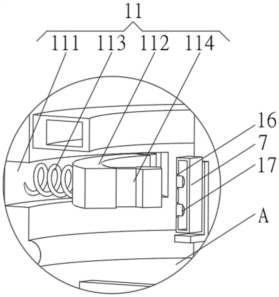
[0032] see Figure 1-4 , the present invention provides a technical solution: on the basis of Embodiment 1, a buffer plate 10 is fixedly connected to one side of the stirring blade 7, and a knocking device 11 is symmetrically installed on the inner wall of the mixing tank 2 near the buffer plate 10, The inside of the stirring fan blade 7 is provided with an inflatable chamber 12, and the inside of the mixing bucket 2 is positioned at the top of the stirring fan blade 7 and is connected with an inflatable ring 13. The inside of the inflatable ring 13 is provided with an inflatable groove 14, and the inflatable groove 14 runs through the inflatable ring 13 and It communicates with the inflatable chamber 12 , the top of the inflatable ring 13 communicates with an inflatable tube 15 , and one side of the stirring blade 7 is uniformly provided with an air jet groove 16 , and the air jet groove 16 communicates with the inflatable groove 14 .

[0033] Knocking device 11 comprises kno...

Embodiment 3

[0036] see Figure 1-5 , the present invention provides a technical solution: on the basis of Embodiment 2, a one-way device 17 is installed inside the air jet groove 16, and the one-way device 17 includes a sealing plug 171, and the sealing plug 171 is slidingly connected with the inner wall of the air jet groove 16, One end of the sealing plug 171 extending to the interior of the air cavity 12 is symmetrically provided with a guide groove 172 .

[0037] One end of the sealing plug 171 extending to the inside of the inflatable cavity 12 is fixedly connected with a contact plate 173, and one side of the contact plate 173 is symmetrically provided with a fan hole 174, and a fan plate 175 is rotatably connected between the two sides of the inner wall of the fan hole 174, One end of the fan plate 175 extends to the inside of the guide groove 172 .

[0038] When in use, the sealing plug 171 blocks the air jet groove 16 to prevent chemical raw materials from entering the interior ...


PUM


Abstract

The invention discloses a chemical raw material stirring device which comprises a base, a stirring barrel is mounted at the top of the base, a driving groove is formed in the top of the base, a driving motor is fixedly connected to the bottom of the inner side of the driving groove, and the output end of the driving motor is connected with a sealing plate. Stirring fan blades are uniformly mounted at the top of the sealing plate through stirring rods, upper rotating plates are uniformly mounted at the top of the sealing plate, a buffer plate is fixedly connected to one side of each stirring fan blade, knocking devices are symmetrically mounted at the positions, close to the buffer plate, of the inner wall of the stirring barrel, and air inflation cavities are formed in the stirring fan blades. The invention relates to the technical field of chemical machinery. According to the chemical raw material stirring device, the purpose of improving the chemical raw material stirring efficiency is achieved; and chemical raw materials are stirred and mixed in multiple modes at the same time, so that particulate matter can be prevented from sinking to the bottom in the stirring process, and the chemical raw materials are stirred more sufficiently.

Description

technical field [0001] The invention relates to the technical field of chemical machinery, in particular to a chemical raw material stirring device. Background technique [0002] A chemical plant is a factory engaged in the chemical industry. The relationship between human beings and chemical industry is very close, and it has spread to all aspects of life. In modern life, chemical products are inseparable almost anytime and anywhere, from material life such as clothing, food, housing, and transportation to Culture, art, entertainment and other spiritual life all need chemical products to serve them. Some chemical products play an epoch-making role in the history of human development. Their production and application even represent a certain historical stage of human civilization. [0003] Before producing products, chemical factories need to mix chemical raw materials to make them more uniform. However, the existing chemical raw material stirring device has a single means o...

Claims


Application Information

Patent Timeline
IPC IPC(8): B01F13/02B01F7/18B01F33/40
Inventor 李桂春
Owner 李桂春
Why Eureka
Try Eureka