Small positioning clamp device operated by one hand

A positioning fixture and one-handed operation technology, which is applied in the direction of workpiece clamping devices, manufacturing tools, etc., can solve the problems of inconvenient adjustment of directional antenna direction adjustment, etc., and achieve the effect of improving the fixing effect, increasing the applicable range, and improving the applicable range

Inactive Publication Date: 2021-10-22
李家豪
View PDF6 Cites 0 Cited by
  • Summary
  • Abstract
  • Description
  • Claims
  • Application Information

AI Technical Summary

Problems solved by technology

[0004] Aiming at the deficiencies of the prior art, the present invention provides a small positioning fixture device operated by one hand, which solves the problem of inconvenient adjustment of the direction of the directional antenna

Method used


Image

  • Small positioning clamp device operated by one hand
  • Small positioning clamp device operated by one hand
  • Small positioning clamp device operated by one hand

Examples


Embodiment Construction

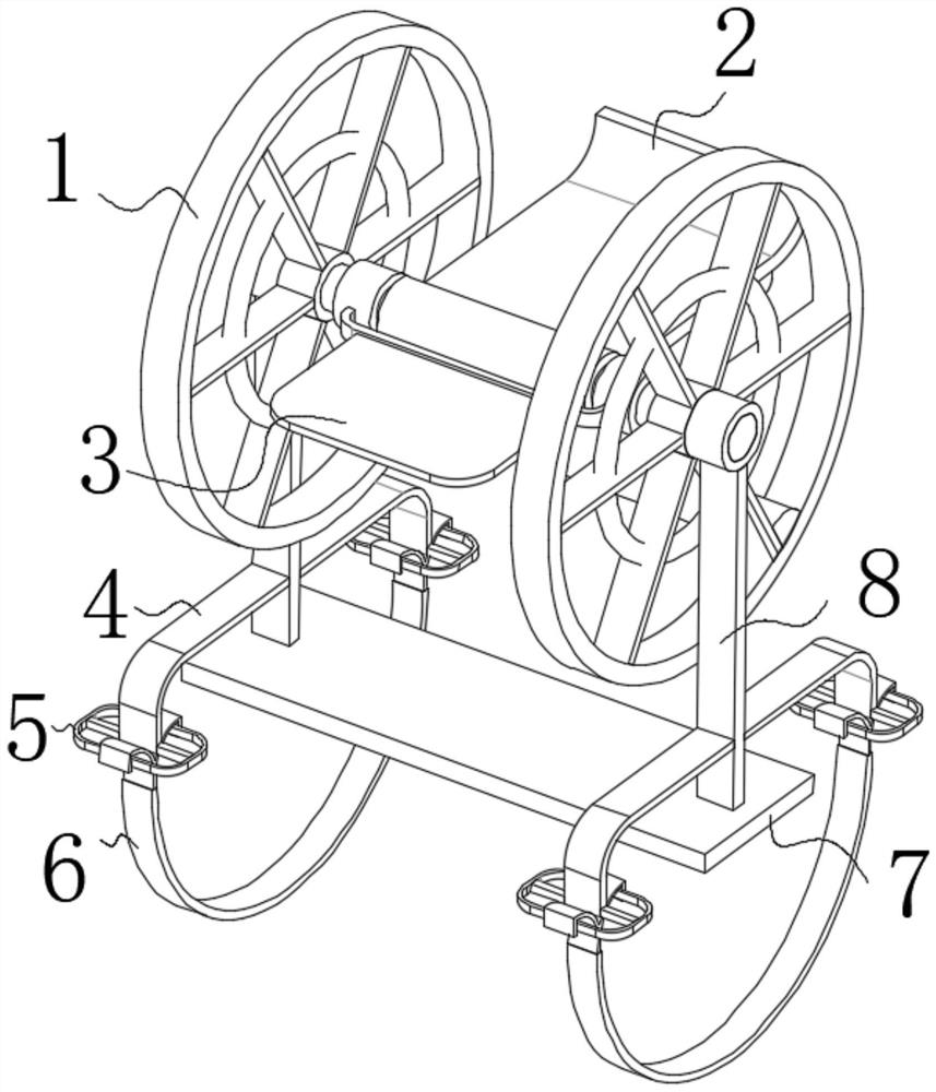
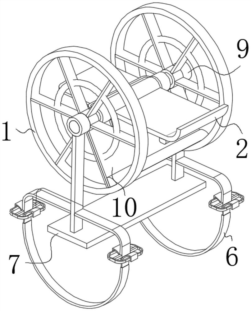
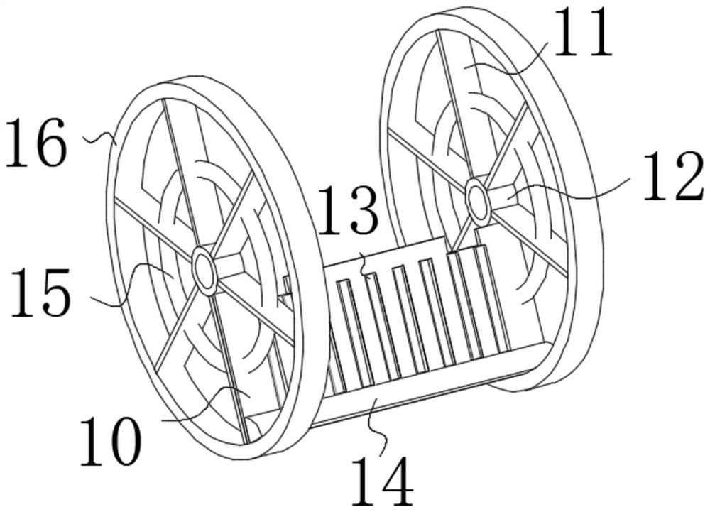
[0023] use Figure 1-Figure 6 A one-handed small positioning jig device according to an embodiment of the present invention will be described as follows.

[0024] Such as Figure 1-Figure 6 As shown, a small positioning fixture device operated by one hand according to the present invention includes a runner 1; , the left side of the fixed plate 2 is provided with a pedal 3, the right end of the pedal 3 is fixedly connected with the outer surface of the runner 1, the two ends of the runner 1 are symmetrically provided with struts 8, and the bottom of the runner 1 is connected with the pole 8 The top is fixedly connected, the bottom of the pole 8 is provided with a base plate 7, and the bottom of the pole 8 is fixedly connected with the top of the base plate 7, the two ends of the pole 8 are symmetrically provided with auxiliary rods 4, and the right end of the auxiliary rod 4 is connected to the pole 8. The left end of the auxiliary rod 4 is fixedly connected, the two ends of...


PUM


Abstract

The invention belongs to the field of positioning clamps, and particularly relates to a small positioning clamp device operated by one hand. The small positioning clamp device comprises rotating wheels, wherein fixing plates are arranged inside the rotating wheels, the outer surfaces of the rotating wheels are movably connected with the left ends of the fixing plates, pedals are arranged on the left sides of the fixing plates, the right ends of the pedals are fixedly connected with the outer surfaces of the rotating wheels, supporting rods are symmetrically arranged at the two ends of the rotating wheels, the bottoms of the rotating wheels are fixedly connected with the tops of the supporting rods, a bottom plate is arranged at the bottoms of the supporting rods, the bottoms of the supporting rods are fixedly connected with the top of the bottom plate, auxiliary rods are symmetrically arranged at the two ends of the supporting rods, the right ends of the auxiliary rods are fixedly connected with the left ends of the supporting rods, stabilizing rings are symmetrically arranged at the two ends of the auxiliary rods, the inner walls of the stabilizing rings are fixedly connected with the bottoms of the auxiliary rods, fixing rings are arranged at the bottoms of the stabilizing rings, the tops of the fixing rings are movably connected with the bottoms of the stabilizing rings, and rolling shafts are symmetrically arranged at the two ends of the rotating wheels.

Description

technical field [0001] The invention belongs to the field of positioning fixtures, in particular to a small positioning fixture device operated by one hand. Background technique [0002] Directional antenna refers to an antenna that transmits and receives electromagnetic waves particularly strongly in one or several specific directions, while transmitting and receiving electromagnetic waves in other directions is zero or extremely small. The purpose of using a directional transmitting antenna is to increase the effective utilization of radiation power and increase confidentiality; the main purpose of using a directional receiving antenna is to enhance signal strength and increase anti-interference ability. However, when testing the azimuth or pitch parameters of equipment such as small directional antennas, the conventionally used fixture devices are clumsy and cumbersome to operate, and are generally adjusted according to regular angles, and stepless positioning cannot be a...

Claims


Application Information

Patent Timeline
Patent Type & Authority Applications(China)
IPC IPC(8): B25B11/00
CPCB25B11/00
Inventor 李家豪
Owner 李家豪
Why Eureka
Try Eureka