Automatic knotting mechanism

A technology of automatic knotting and threading, applied in binding and other directions, can solve the problem of low efficiency and achieve the effect of reducing work intensity, wide application range, and improving quality and consistency

Active Publication Date: 2021-10-22
SUZHOU DEQI INTELLIGENT TECH CO LTD
View PDF5 Cites 0 Cited by
  • Summary
  • Abstract
  • Description
  • Claims
  • Application Information

AI Technical Summary

Problems solved by technology

Since the threading and knotting of the files is mostly manu

Method used


Image

  • Automatic knotting mechanism
  • Automatic knotting mechanism
  • Automatic knotting mechanism

Examples


Embodiment 1

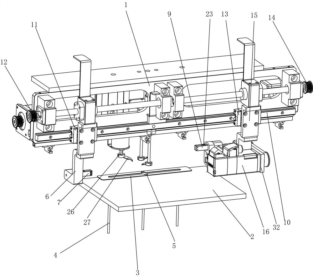
[0055] An improvement is made to an automatic knotting mechanism provided by the present invention. The translation device includes an X-axis translation track 10 erected on the bracket 1, a left ball screw assembly 12 that drives the left slider 11 to slide along the X-axis translation track 10, and The right ball screw assembly 14 that drives the right slider 13 to slide along the X-axis translation track 10, the left ball screw assembly 12 and the left slider 11 are connected by the left connecting plate 6, the right ball screw assembly 14 and the right slide The blocks 13 are connected by the right connecting plate 15, and the bottom of the right connecting plate 15 is connected with an overturning device, so that the translation device can drive the left threading device and the right threading device through the left ball screw assembly 12 and the right ball screw assembly 14 respectively. The device moves relatively or oppositely along the X-axis translation track 10. Th...

Embodiment 2

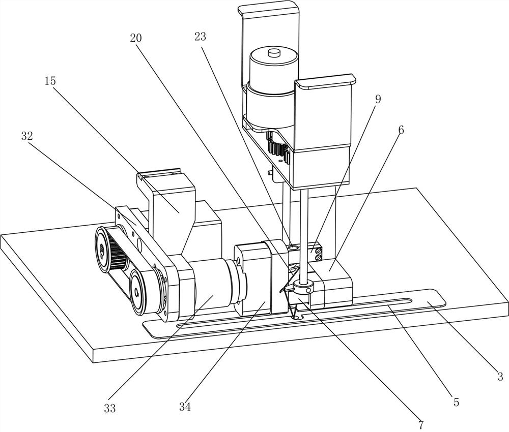
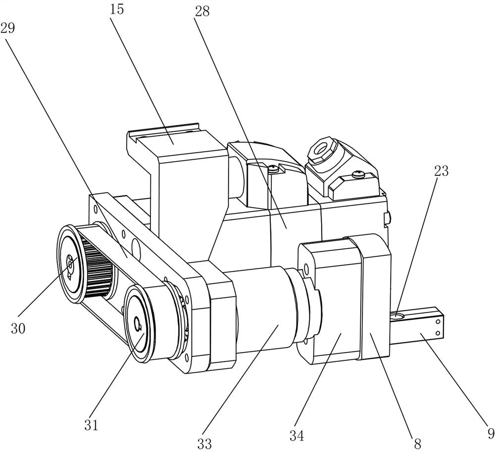
[0081] An improvement is made to an automatic knotting mechanism provided by the present invention. Two card slots 17 are respectively electrically connected to the two electromagnetic absorbers in the electromagnetic adsorption seat 34 on the turnover plate 8, and the electromagnetic adsorption is fixed in one of the card slots. Hold one end of the right handover rod 9, and another empty draw-in slot is set as the handover place, like this, after the flipping plate 8 is turned over for the first time, the empty draw-in slot at the handover place can replace the card where the original right handover stick 9 is located. The slot is towards the left transfer rod 7, at this moment, the electromagnetic adsorber on the left connecting plate 6 desorbs one end of the left transfer rod 7, and the electromagnetic adsorber on the electromagnetic adsorption seat 34 produces electromagnetic adsorption in the draw-in groove at the transfer point simultaneously, In this way, the other end o...

Embodiment 3

[0106] A further improvement is made to the automatic knotting mechanism provided by the present invention. In order to successfully complete the handover of the left transfer rod 7 and the right transfer rod 9 through the flip plate 8, two card slots 17 are distributed on the flip plate 8 in axisymmetric manner. , the flipping plate 8 takes the axis of symmetry between the two card slots 17 as the flipping axis to turn over an angle of 180°, which can ensure that the flipping plate 8 is turned over once and the two card slots are interchanged, and the flipping plate 8 is flipped twice. After two times, the two card slots can return to the position before flipping.

[0107] The operation process of an automatic knotting mechanism provided in Embodiment 3 is described in the following steps:

[0108] 1. Top rope device

[0109] ① A number of thimbles 4 located below the platform 2, and a number of thimbles 4 are distributed on the same horizontal line from left to right;

[0...


PUM


Abstract

The invention relates to an automatic knotting mechanism. A translation device capable of respectively driving a left stringing device and a turnover device to move face to face or back to back is erected on a bracket, and the left stringing device comprises a left crossing rod which is electromagnetically attracted on the side surface of a left connecting plate; a right stringing device comprises a right crossing rod which is electromagnetically attracted to the turnover device and is arranged opposite to the left crossing rod, two ends of a rope are fixed to the left crossing rod and the right crossing rod respectively, and the turnover device is further provided with a crossing position which is in butt joint with the left crossing rod after overturning and electromagnetically attracts the left crossing rod; and an ejector pin penetrates through a platform and jacks the middle section of the rope to form a rope hole, and a rope dividing device comprises a rope dividing assembly used for expanding and twisting the rope hole so that the left crossing rod or the right crossing rod can penetrate through a rope dividing assembly.

Description

technical field [0001] The invention relates to the technical field of a mechanical mechanism, in particular to an automatic knotting mechanism. Background technique [0002] The document binding equipment of the prior art is widely used in fields such as file binding, file binding, document scanning, and document extension. Due to manual or semi-automatic processing when dealing with file threading and knotting, the efficiency of knotting is not high. [0003] In view of the above-mentioned defects, the designer actively researches and innovates, in order to create a kind of automatic knotting mechanism with more industrial utilization value. Contents of the invention [0004] In order to solve the above technical problems, the object of the present invention is to provide an automatic knotting mechanism for automatically threading and knotting document materials. [0005] An automatic knotting mechanism of the present invention includes a bracket, a platform, a transla...

Claims


Application Information

Patent Timeline
IPC IPC(8): B42B2/02B42B2/04B42B2/08
CPCB42B2/02B42B2/04B42B2/08
Inventor 洪健
Owner SUZHOU DEQI INTELLIGENT TECH CO LTD
Why Eureka
Try Eureka