An automatic knotting mechanism
A technology of automatic knotting and threading, applied in binding and other directions, can solve the problem of low efficiency, reduce work intensity, improve quality and consistency, and have a wide range of applications
- Summary
- Abstract
- Description
- Claims
- Application Information
AI Technical Summary
Problems solved by technology
Method used
Image
Examples
Embodiment 1
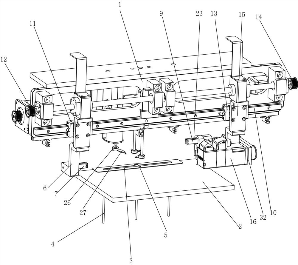
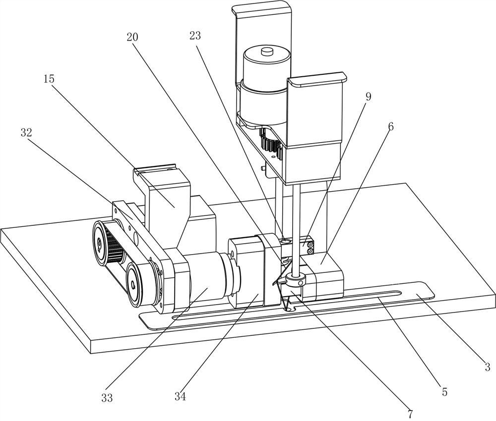
[0055] An improvement is made to an automatic knotting mechanism provided by the present invention. The translation device includes an X-axis translation track 10 erected on the bracket 1, a left ball screw assembly 12 that drives the left slider 11 to slide along the X-axis translation track 10, and The right ball screw assembly 14 that drives the right slider 13 to slide along the X-axis translation track 10, the left ball screw assembly 12 and the left slider 11 are connected by the left connecting plate 6, the right ball screw assembly 14 and the right slide The blocks 13 are connected by the right connecting plate 15, and the bottom of the right connecting plate 15 is connected with an overturning device, so that the translation device can drive the left threading device and the right threading device through the left ball screw assembly 12 and the right ball screw assembly 14 respectively. The device moves relatively or oppositely along the X-axis translation track 10. Th...
Embodiment 2
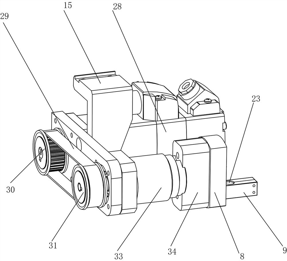
[0081] An improvement is made to an automatic knotting mechanism provided by the present invention. Two card slots 17 are respectively electrically connected to the two electromagnetic absorbers in the electromagnetic adsorption seat 34 on the turnover plate 8, and the electromagnetic adsorption is fixed in one of the card slots. Hold one end of the right handover rod 9, and another empty draw-in slot is set as the handover place, like this, after the flipping plate 8 is turned over for the first time, the empty draw-in slot at the handover place can replace the card where the original right handover stick 9 is located. The slot is towards the left transfer rod 7, at this moment, the electromagnetic adsorber on the left connecting plate 6 desorbs one end of the left transfer rod 7, and the electromagnetic adsorber on the electromagnetic adsorption seat 34 produces electromagnetic adsorption in the draw-in slot at the transfer point simultaneously, In this way, the other end of ...
Embodiment 3
[0106] A further improvement is made to the automatic knotting mechanism provided by the present invention. In order to successfully complete the handover of the left transfer rod 7 and the right transfer rod 9 through the flip plate 8, two card slots 17 are distributed on the flip plate 8 in axisymmetric manner. , the flipping plate 8 takes the axis of symmetry between the two card slots 17 as the flipping axis to turn over an angle of 180°, which can ensure that the flipping plate 8 is turned over once and the two card slots are interchanged, and the flipping plate 8 is flipped twice. After two times, the two card slots can return to the position before flipping.
[0107] The operation process of an automatic knotting mechanism provided in Embodiment 3 is described in the following steps:
[0108] 1. Top rope device
[0109] ① A number of thimbles 4 located below the platform 2, and a number of thimbles 4 are distributed on the same horizontal line from left to right;
[0...
PUM
 Abstract
Description
Claims
Application Information
 - R&D
- Intellectual Property
- Life Sciences
- Materials
- Tech Scout
- Unparalleled Data Quality
- Higher Quality Content
- 60% Fewer Hallucinations
Browse by: Latest US Patents, China's latest patents, Technical Efficacy Thesaurus, Application Domain, Technology Topic, Popular Technical Reports.
© 2025 PatSnap. All rights reserved.Legal|Privacy policy|Modern Slavery Act Transparency Statement|Sitemap|About US| Contact US: help@patsnap.com


