Ladder-type sleepers and railway tracks

A sleeper and ladder-type technology, which is applied in the field of sleepers, can solve the problems of exacerbated train vibration, deterioration of running stability and riding comfort, and achieve the effects of reducing workload, overcoming labor shortage, and enhancing bending rigidity

Inactive Publication Date: 2004-01-21
RAILWAY TECH RES INST
View PDF1 Cites 13 Cited by
  • Summary
  • Abstract
  • Description
  • Claims
  • Application Information

AI Technical Summary

Problems solved by technology

The larger deformation of these rails will aggravate the vibration of t

Method used


Image

  • Ladder-type sleepers and railway tracks
  • Ladder-type sleepers and railway tracks
  • Ladder-type sleepers and railway tracks

Examples


Embodiment Construction

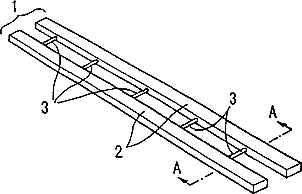
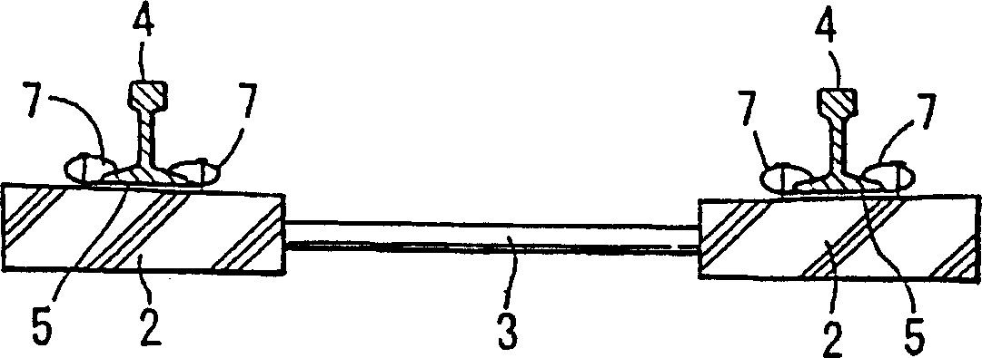
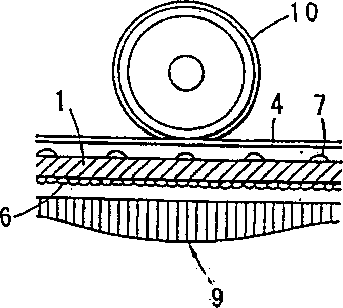
[0049] figure 1 It is a configuration diagram showing Embodiment 1 of the present invention. figure 2 is along figure 1 A cross-sectional view taken along line A-A in . Figure 3A with 3BIt is a diagram showing the distribution state of the ballast pressure of the ladder-type sleeper track structure of Example 1 and the distribution state of the ballast pressure of the conventional transverse sleeper-type track structure, respectively. In the figure, 1 is a ladder-type sleeper, 2 is a longitudinal beam, 3 is a connector connecting the longitudinal beam 2, 4 is a rail, and 5 is a rail pad placed between the rail 4 and the longitudinal beam 2 to absorb vibration (such as elastic material made of calibration film), 6 is the ballast buried in the ladder sleeper, 7 is the rail fastening device for connecting the rail 4 to the longitudinal beam 2, 8 is a conventional transverse sleeper, 10 is a wheel.

[0050] The ladder-type sleeper 1 of this embodiment comprises a pair of lo...


PUM


Abstract

The present invention comprises longitudinal beams provided on the underside of each of a pair of rails in the longitudinal direction of the rails and multiple connectors which mutually connect these longitudinal beams at designated spacings along the longitudinal direction. Because the ladder-type sleepers of the present invention have a structure wherein longitudinal beams are continuously positioned along the longitudinal direction of the rails, the bending stiffness of the track frame in the longitudinal direction increases, and the ballast pressure is reduced by improving the distribution of the train load. As a result, it is possible to reduce track irregularities resulting from the repeated burden of the train load.

Description

technical field [0001] The present invention relates to railway tracks and sleepers for railway tracks. Background technique [0002] Fig. 16 is a structural diagram of a conventional ballast railway track using transverse sleepers. Among the figure, 4 is a rail, 6 is ballast, 7 is a rail fastener, and 8 is a transverse sleeper. Conventional ballast railways comprise a structure in which the track frame consists of one-piece or two-section transverse sleepers 8 placed transversely with respect to the rails. The load of the train on the longitudinal and lateral directions of the rail is supported by the bearing pressure and friction of the ballast. [0003] The aforementioned conventional track using transverse sleepers is prone to track deformation due to being severely affected by repeated loads from trains. As a result, this deformation increases the vibration of the train, deteriorating running stability and ride comfort. Therefore, regular maintenance is required to ...

Claims


Application Information

Patent Timeline
IPC IPC(8): E01B3/38
CPCE01B3/38E01B3/00
Inventor 湧井一松本信之井上宽美
Owner RAILWAY TECH RES INST
Why Eureka
Try Eureka