Method for detecting form of chip in charging tray based on fringe projection 3D imaging

A detection method and fringe projection technology, which is applied in the direction of measuring devices, analyzing materials, and optical testing for defects/defects, can solve the problems of reducing false detection rate, missed detection rate, difficult to solve overlapping materials, and failure to meet customer needs, etc., to achieve reduction Missing detection rate, fast effect

Active Publication Date: 2021-10-22
HEFEI TUXUN ELECTRONICS TECH
View PDF9 Cites 1 Cited by
  • Summary
  • Abstract
  • Description
  • Claims
  • Application Information

AI Technical Summary

Problems solved by technology

Existing 2D inspection methods are detected by optical photography above the material tray. Optical photography is difficult to solve the problem of overlapping materials, and cannot be compatible with all defect effects
[0003] In view of the above defects, the existing 2D detection algorithm can no longer meet the actual detection needs, and at the same time, the false detection rate is high and the missed detection rate cannot meet customer needs.
And there is no domestic 3D detection equipment at present, so in order to meet customer needs, a 3D detection method has been developed, which greatly reduces the false detection rate and missed detection rate

Method used


Image

  • Method for detecting form of chip in charging tray based on fringe projection 3D imaging
  • Method for detecting form of chip in charging tray based on fringe projection 3D imaging
  • Method for detecting form of chip in charging tray based on fringe projection 3D imaging

Examples


Embodiment Construction

[0033] The following will clearly and completely describe the technical solutions in the embodiments of the present invention with reference to the accompanying drawings in the embodiments of the present invention. Obviously, the described embodiments are only some, not all, embodiments of the present invention. Based on the embodiments of the present invention, all other embodiments obtained by persons of ordinary skill in the art without making creative efforts belong to the protection scope of the present invention.

[0034] The invention provides a method for detecting the shape of chips in a tray based on fringe projection 3D imaging. The detection method specifically detects whether there is a product in the tray and whether the position of the product in the tray is correct.

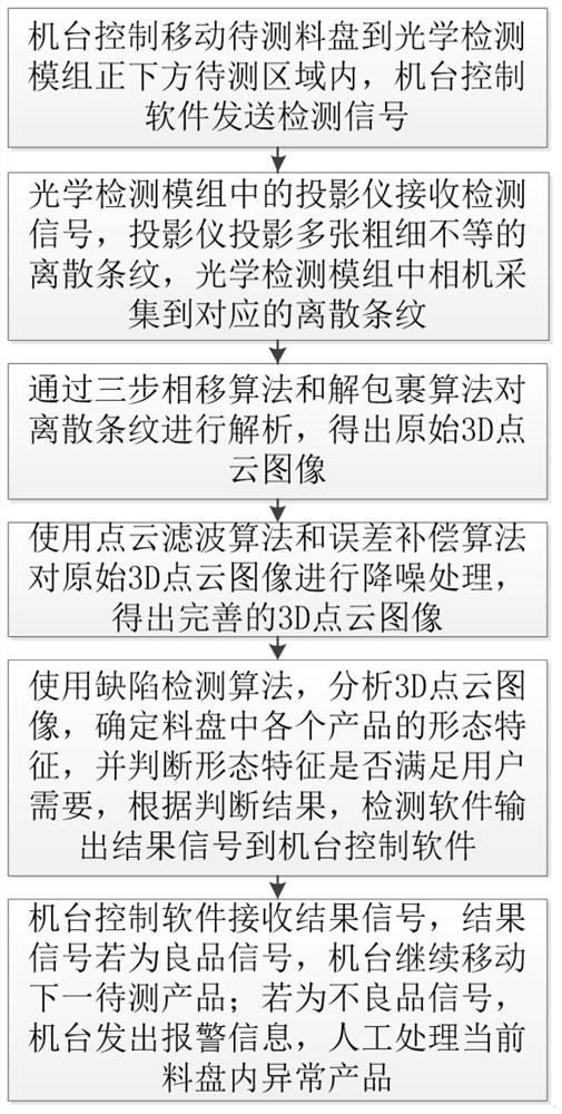
[0035] Such as figure 1 As shown, it specifically includes the following steps:

[0036] The machine control moves the material tray to be tested to the area to be tested directly under the optic...


PUM


Abstract

The invention discloses a method for detecting the form of a chip in a charging tray based on fringe projection 3D imaging, and the key points of the technical scheme are as follows: an out-of-focus fringe projection technology and a binocular vision camera calibration technology are adopted for imaging, so that the false detection rate and the omission rate are reduced, and the problems of empty materials, warping materials, stacking materials and the like in production are solved; meanwhile, a three-step phase shift algorithm and an unwrapping algorithm are used, and a perfect 3D point cloud image is obtained. An error compensation algorithm and a filtering algorithm are used, so that the 3D image processing is more perfect. Defects in the 3D picture are screened by using a defect detection algorithm; four cameras are arranged, the view field is fully paved on the whole charging tray, and the problem of the whole charging tray can be solved through one-time detection. And compared with a 2D detection scheme, the speed is higher. According to the method, the requirements of customers are met, meanwhile, a brand-new 3D detection method is designed, the detection method has the 3D detection function of detecting whether products exist in the charging tray or not and whether the positions of the products in the charging tray are correct or not, and the false detection rate and the omission ratio are greatly reduced.

Description

technical field [0001] The invention belongs to the technical field of chip detection, and in particular relates to a method for detecting the shape of chips in a tray based on fringe projection 3D imaging. Background technique [0002] At present, IC testing, packaging, baking and other processes all use trays as containers. There are various types of trays, and the types of defects in the contents are ever-changing. Problems such as empty materials, warped materials, and stacked materials usually occur. Existing 2D inspection methods use optical photography above the material tray to detect. Optical photography is difficult to solve the problem of overlapping materials, and cannot be compatible with all defect effects. [0003] In view of the above defects, the existing 2D detection algorithm can no longer meet the actual detection needs, and at the same time, the high false detection rate and missed detection rate cannot meet customer needs. And there is no domestic 3D d...

Claims


Application Information

Patent Timeline
Patent Type & Authority Applications(China)
IPC IPC(8): G01B11/25G01B11/245G01B11/00G01N21/88
CPCG01B11/254G01B11/245G01B11/2545G01B11/002G01N21/8851G01N21/8806G01N2021/8887G01N2021/888Y02P90/30
Inventor 洪敬柱李林林郑飞
Owner HEFEI TUXUN ELECTRONICS TECH
Why Eureka
Try Eureka