
A new material tensile strength testing equipment

A technology for testing equipment and tensile strength, which is used in the application of stable tension/pressure to test the strength of materials, analyze materials, strength characteristics, etc. problems, to achieve the effect of prolonging the service life, preventing debris from splashing, and preventing the material from slipping

Active Publication Date: 2021-11-19
南通恒鑫新材料有限公司
View PDF9 Cites 0 Cited by
  • Summary
  • Abstract
  • Description
  • Claims
  • Application Information

AI Technical Summary

Problems solved by technology

[0003] Existing tensile strength testing equipment will generate large vibrations when the material to be tested breaks, which will cause damage to the precision parts in the equipment, and the existing tensile strength testing equipment will adapt to highly elastic materials in the future, and the tensile The strokes are designed to be very large, which makes the height of the equipment relatively high and occupies a large space, and the fixture is also easy to clamp the material, and can only measure the tensile strength of the material at room temperature, and the tensile strength at different temperatures cannot be measured. In the measurement, the flying debris was not intercepted when the measurement material was broken, and the debris easily entered some mechanisms and affected the operation of the mechanism

Method used


Image

  • A new material tensile strength testing equipment
  • A new material tensile strength testing equipment
  • A new material tensile strength testing equipment

Examples


Embodiment Construction

[0035] The present invention will be further explained and described below in conjunction with the accompanying drawings and specific embodiments of the description. For the step numbers in the embodiment of the present invention, it is only set for the convenience of explanation and description, and there is no limitation on the order of the steps. The execution order of each step in the embodiment can be carried out according to the understanding of those skilled in the art Adaptive adjustments:

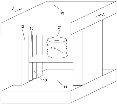
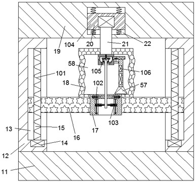
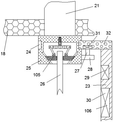
[0036] Refer to attached Figure 1-6 , a new material tensile strength testing device according to an embodiment of the present invention, comprising a body casing 11, the top wall of the body casing 11 is fixed with left and right symmetrical support blocks 12, and the support blocks 12 are provided with The tension beam 16, the support block 12 is provided with a power device 101 capable of moving the tension beam 16 up and down, the tension beam 16 is fixed with a first fixed b...


PUM


Abstract

The invention discloses a new material tensile strength testing device, which comprises a machine body casing. The top wall of the body casing is fixed with left and right symmetrical support blocks, tension beams are arranged between the support blocks, and tension beams are arranged inside the support blocks to A power device that moves up and down. The tension beam is fixed with a first fixed block that runs through the upper and lower surfaces of the tension beam. The first fixed block is provided with a first clamping cavity that runs through the upper and lower surfaces of the first fixed block. The first clamping cavity There is a first clamping block; the first clamping block and the second clamping block provided in the present invention cooperate with each other to detect materials with greater elasticity, and can shorten the stretching stroke, so that the height of the present invention is reduced and the occupied space is saved. Space, the third clamping block that is provided with under the action of the second limit chute and reverse tooth can close to each other tightly clamp the material with the downward movement of the stretched material to prevent the material from slipping.

Description

technical field [0001] The invention relates to the technical field of material strength detection, in particular to a new material tensile strength detection device. Background technique [0002] Tensile strength is the critical value of the transition of metal from uniform plastic deformation to local concentrated plastic deformation, and it is also the maximum bearing capacity of the material under static tensile conditions. Tensile strength is the resistance to the maximum uniform plastic deformation of the material. Before bearing the maximum tensile stress, the deformation is uniform and consistent, but after exceeding, the material begins to appear necking phenomenon, that is, concentrated deformation occurs. For brittle materials without uniform plastic deformation, it reflects the fracture resistance of the material, so when the material is produced , need to be tested. [0003] Existing tensile strength testing equipment will generate large vibrations when the mat...

Claims


Application Information

Patent Timeline
Patent Type & Authority Patents(China)
IPC IPC(8): G01N3/08G01N3/02G01N3/04
CPCG01N3/08G01N3/02G01N3/04G01N2203/0017
Inventor 吴国新
Owner 南通恒鑫新材料有限公司
Learn More