Barrel casing pump and method for manufacturing barrel casing pump

A shell and sheath technology, which is applied to components of pumping devices for elastic fluids, engine manufacturing, pumps, etc., can solve problems such as increased manufacturing costs, and achieve the effects of low manufacturing and easy cost.

Pending Publication Date: 2021-10-22
KSB AG
View PDF0 Cites 0 Cited by
  • Summary
  • Abstract
  • Description
  • Claims
  • Application Information

AI Technical Summary

Problems solved by technology

As a result, the pump construction with the screw insert is considerably larger than the pump construction with conventional flow chambers, which can ultimately lead to a decisive increase in the production costs precisely for pump types with a larger construction.

Method used


Image

  • Barrel casing pump and method for manufacturing barrel casing pump
  • Barrel casing pump and method for manufacturing barrel casing pump
  • Barrel casing pump and method for manufacturing barrel casing pump

Examples


Embodiment Construction

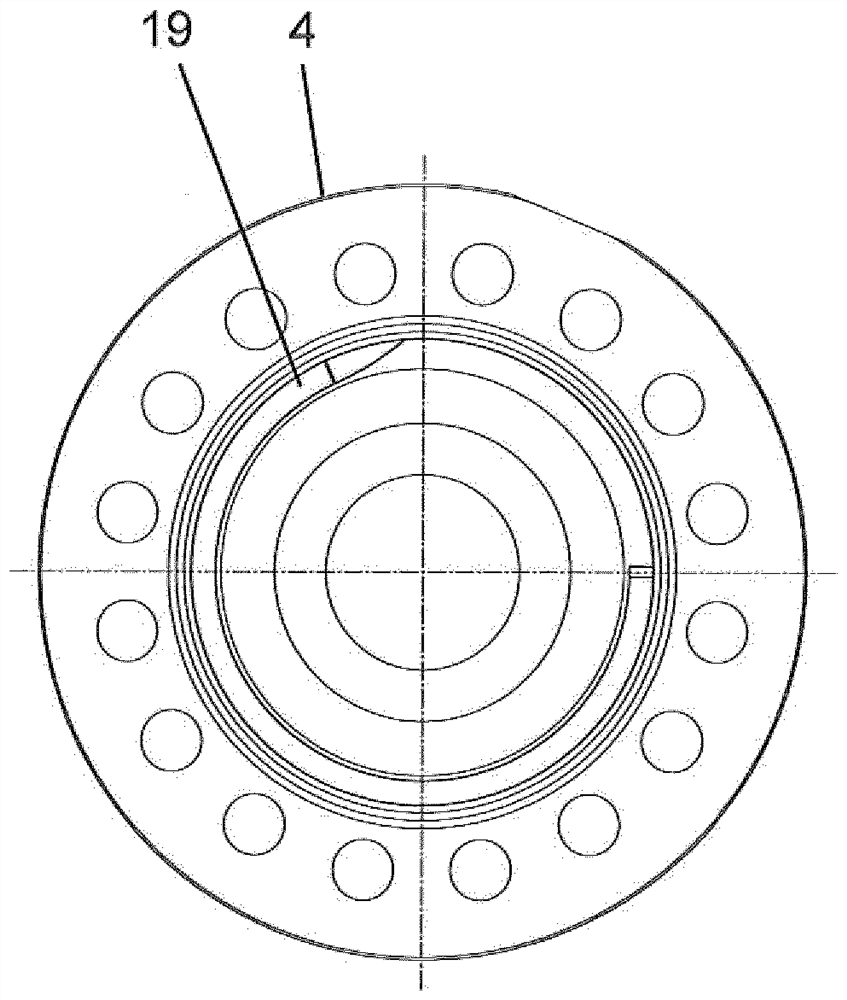
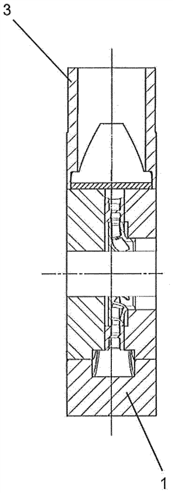
[0031] figure 1 A rotary pump is shown with a jacket housing 1 which has both a suction connection 2 and a pressure connection 3 . The jacket housing 1 is closed at its pressure-side end by a cover 4 , which is fastened, in particular screwed, to the jacket housing 1 by means of connecting means 5 .

[0032] Arranged in the jacket housing 1 is an insert having a shaft 6 arranged rotatably about an axis A of rotation. A plurality of impellers 7, 7' are arranged one behind the other on the shaft 6, whereby individual pump stages, here five pump stages, are formed. Each pump stage additionally has a stationary guide wheel 8, wherein the last guide wheel seen in the direction of flow is designated with the reference numeral 8'. The closest impeller to the pressure connection 3 or, seen in the direction of flow, the last impeller is marked with the reference numeral 7'. Said working wheels 7, 7' are radial wheels in this embodiment. As an alternative, for example, semi-axial wh...


PUM


Abstract

The invention relates to a centrifugal pump having a barrel casing (1) and at least one stage casing (9, 9') inserted therein, wherein in the transition from the last stage casing (9') to the pressure connector (3) a spiral flow space is formed by a contour of the last stage casing (9'), a contour of a cover (4) which closes the barrel casing (1) on an end face and the inner contour of the barrel casing (1).

Description

technical field [0001] The invention relates to a rotary pump having a jacket housing and at least one stepped housing inserted therein. Background technique [0002] Such rotary pumps, which are also called double casing pumps or sheath casing pumps, are rotary pumps which are surrounded by a jacket-shaped casing. The sheath housing provided with the suction connection and the pressure connection is closed with a cover in a plane perpendicular to the axis. These are generally multistage pumps, which are used as high-pressure pumps and very high-pressure pumps, in particular also as boiler feed pumps. Inside the sheath housing, a plurality of graded housings are arranged successively in the axial direction in series. Each stepped casing includes a pump impeller and optionally a stationary stator. [0003] The individual stepped casings are generally configured together with the pump shaft as an associated pump insert. The flow transition from the last guide wheel or the ...

Claims


Application Information

Patent Timeline
Patent Type & Authority Applications(China)
IPC IPC(8): F04D1/06F04D29/44F04D29/42
CPCF04D1/063F04D29/445F04D29/426F05D2250/52
Inventor P·阿曼H·卢茨
Owner KSB AG
Why Eureka
Try Eureka