
Positioning and connecting structure, cutter assembly, cutter head and cutter rod

A technology of connecting structure and tool assembly, which is applied in the attachment of tool holder, tool for lathe, manufacturing tool, etc., can solve the problems of high requirements on manufacturing accuracy, high production cost, and the existence of gaps in matching, and achieve manufacturing accuracy. The effect of reduced requirements, easy manufacturing, high connection positioning accuracy

Pending Publication Date: 2021-10-26
苏州咖多切削刀具有限公司
View PDF0 Cites 0 Cited by
  • Summary
  • Abstract
  • Description
  • Claims
  • Application Information

AI Technical Summary

Problems solved by technology

[0003] In the existing technology, most of the matching methods between the connecting shaft and the connecting hole are shaft-hole clearance fit. No matter how precise the shaft-hole fit is, due to the problem of tolerance, there is always a gap in the fit, and it is impossible to achieve zero clearance and zero error fit.
In addition, there is another kind of matching for over-positioning taper surface. This kind of matching method has high requirements on the manufacturing accuracy of the connecting part of the parts, and the production cost is very high.

Method used


Image

  • Positioning and connecting structure, cutter assembly, cutter head and cutter rod
  • Positioning and connecting structure, cutter assembly, cutter head and cutter rod
  • Positioning and connecting structure, cutter assembly, cutter head and cutter rod

Examples


Embodiment Construction

[0028] The following will clearly and completely describe the technical solutions in the embodiments of the present invention with reference to the accompanying drawings in the embodiments of the present invention. Obviously, the described embodiments are only some of the embodiments of the present invention, not all of them. Based on the embodiments of the present invention, all other embodiments obtained by persons of ordinary skill in the art without making creative efforts belong to the protection scope of the present invention.

[0029] It should be noted that in the description of the present invention, terms such as "first" and "second" are only used to describe the purpose and distinguish similar objects, there is no sequence between the two, and they cannot be interpreted as indicating or imply relative importance. In addition, in the description of the present invention, unless otherwise specified, "plurality" means two or more.

[0030] The present invention provid...


PUM


Abstract

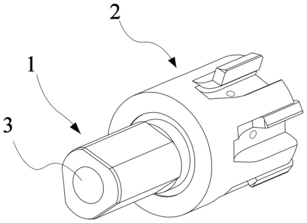
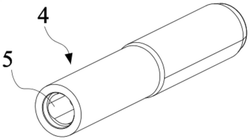
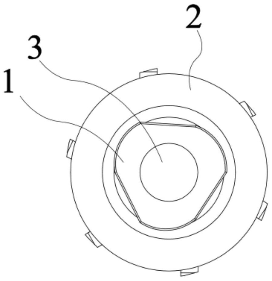
The invention provides a positioning and connecting structure, a cutter assembly, a cutter head and a cutter rod. The positioning and connecting structure comprises a part I and a part II; the part I comprises a connecting shaft; the part II is provided with a connecting hole; the connecting shaft can be inserted into the connecting hole; the side wall of the connecting shaft comprises a plurality of inner arc surfaces; the inner wall of the connecting hole comprises a plurality of outer arc surfaces; the connecting shaft can rotate relative to the connecting hole to the positions where the inner arc surfaces are tangent to the outer arc surfaces correspondingly; and the connecting shaft can be prevented from further rotating around the same direction relative to the connecting hole. According to the positioning and connecting structure provided by the invention, high-precision connection between parts in assembly is achieved, zero clearance and zero error of the parts can be achieved, convenience and rapidness are achieved, and particularly high-precision connection between long parts is achieved.

Description

technical field [0001] The invention relates to the field of mechanical connection, in particular to a positioning connection structure, a cutter assembly, a cutter head and a cutter rod. Background technique [0002] The statements in this section only provide background information related to the present disclosure and may not constitute prior art. [0003] In the prior art, most of the matching methods between the connecting shaft and the connecting hole are shaft-hole clearance fit. No matter how precise the shaft-hole fit is, due to tolerance problems, there is always a gap in the fit, and it is impossible to achieve zero-clearance and zero-error fit. In addition, there is another kind of matching for over-positioning taper surfaces. This kind of matching method requires high manufacturing accuracy of the connecting parts of the parts, and the production cost is very high. [0004] It should be noted that the above introduction of the technical background is only for t...

Claims


Application Information

Patent Timeline
Patent Type & Authority Applications(China)
IPC IPC(8): B23B27/00
CPCB23B27/00
Inventor 王亚新王文龙贲智军
Owner 苏州咖多切削刀具有限公司
Learn More