Punching device, punching platform and punching method

A punching device and punching device technology, applied in metal processing, electrical components, printed circuit manufacturing, etc., can solve problems such as damage to inner circuit boards, and achieve the effect of avoiding damage and facilitating transportation

Pending Publication Date: 2021-10-26
东莞王氏港建机械有限公司
View PDF0 Cites 1 Cited by
  • Summary
  • Abstract
  • Description
  • Claims
  • Application Information

AI Technical Summary

Problems solved by technology

[0004] The purpose of the embodiment of the present application is to provide a punching device, aiming at solving the problem of damage caused by the inner layer circuit board being lifted up

Method used

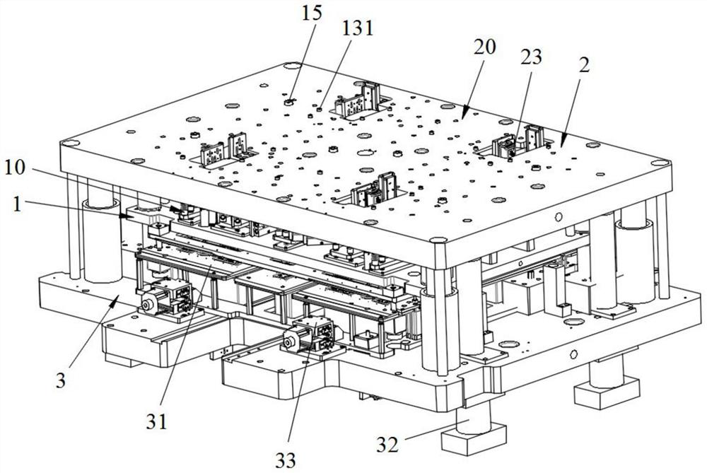
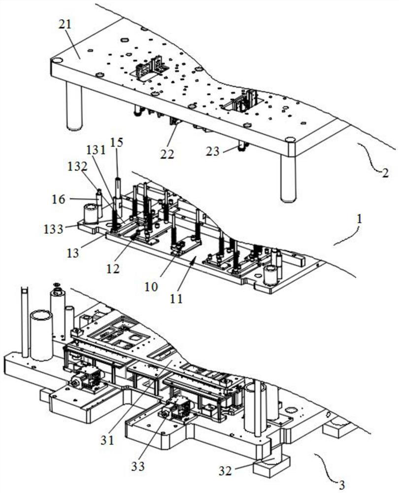
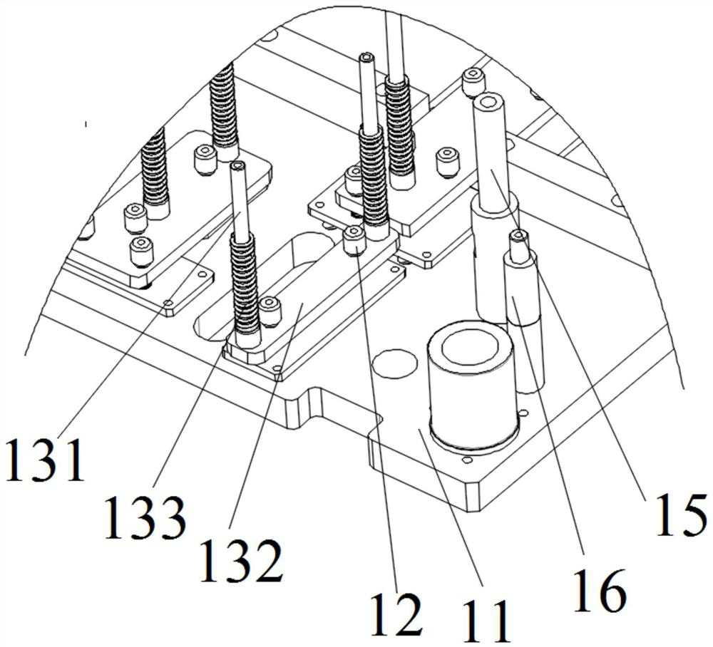

Image

  • Punching device, punching platform and punching method
  • Punching device, punching platform and punching method
  • Punching device, punching platform and punching method

Examples


Embodiment Construction

[0050] In order to make the technical problems, technical solutions and beneficial effects to be solved by the present application clearer, the present application will be further described in detail below in conjunction with the accompanying drawings and embodiments. It should be understood that the specific embodiments described here are only used to explain the present application, and are not intended to limit the present application.

[0051]It should be noted that when an element is referred to as being “fixed” or “disposed on” another element, it may be directly on the other element or be indirectly on the other element. When an element is referred to as being "connected to" another element, it can be directly connected to the other element or indirectly connected to the other element.

[0052] It is to be understood that the terms "length", "width", "top", "bottom", "front", "rear", "left", "right", "vertical", "horizontal", "top" , "bottom", "inner", "outer" and othe...


PUM


Abstract

A punching device comprises a pressing plate structure, a punching needle structure and a needle supporting structure; the pressing plate structure is connected to a stamping device and moves along with the stamping device; the punching needle structure is movably connected to the pressing plate structure; one end of the needle punching structure is connected to the stamping device and moves along with the stamping device; the other end of the needle punching structure supports the punching needle structure, and the stamping device drives the pressing plate structure, the needle supporting structure and the punching needle structure to move towards a workpiece; the pressing plate structure presses the workpiece; the punching needle structure penetrates through the pressing plate structure and completes punching on the workpiece; the stamping device drives the needle supporting structure to move by deviating from the workpiece, and the needle supporting structure supports the punching needle structure to be separated from the workpiece; and the pressing plate structure continues to press the workpiece, and after the punching needle structure moves to a preset distance by deviating from the workpiece, the stamping device drives the pressing plate structure to be separated from the workpiece. Through the arrangement of the needle supporting structure, the stamping device can drive the pressing plate structure to be separated from the workpiece only after the punching needle structure moves to the preset distance by deviating from the workpiece, and therefore the workpiece is effectively prevented from being taken up, damage to the workpiece is effectively avoided, and follow-up conveying of the workpiece is facilitated.

Description

technical field [0001] The invention belongs to the technical field of punching equipment, and in particular relates to a punching device, a punching platform and a punching method. Background technique [0002] When processing inner circuit boards, individual circuit boards need to be glued together with high precision in order to assemble the final circuit. It is therefore increasingly necessary to mark and punch holes on individual inner circuit board layers, usually by punching and drilling holes at precisely defined positions on the printed circuit board to form these markings and holes. [0003] After the traditional stamping platform punches the inner circuit board, the pressure plate for pressing the inner circuit board and the punching needle for punching are separated from the inner circuit board at the same time, and both are separated from the inner circuit board at the same time, which greatly It may bring up the inner circuit board, which may cause damage to t...

Claims


Application Information

Patent Timeline
Patent Type & Authority Applications(China)
IPC IPC(8): B26F1/14B26F1/24B26D7/01B26D7/02H05K3/00
CPCB26F1/14B26F1/24B26D7/015B26D7/02H05K3/005
Inventor 霍锦充
Owner 东莞王氏港建机械有限公司
Why Eureka
Try Eureka