Moisture absorber for transformer expansion tank

A transformer oil and moisture absorber technology, applied in the field of transformers, can solve the problems of silica gel deterioration, shortened service life, and the use of silica gel is not optimal, so as to reduce oil content, reduce continuous moisture absorption, and avoid color change. Effect

Inactive Publication Date: 2021-10-26
郭渗渗
View PDF0 Cites 0 Cited by
  • Summary
  • Abstract
  • Description
  • Claims
  • Application Information

AI Technical Summary

Problems solved by technology

[0003] 1. The existing dehumidifier is mainly composed of a glass jar filled with silica gel and a bottom cover filled with transformer oil at the bottom. When the external air enters, it needs to be removed by the transformer oil and then absorbed by the silica gel. The top of this structure It is directly in contact with the connecting pipe, and the air in the oil conservator is discharged at high temperature, and at this time the air is in contact with the high temperature transformer oil, resulting in a lot of oil molecules in the air, so that it contacts with silica gel when discharged It will lead to adsorption on silica gel, which will cause deterioration of silica gel, reduce its service life and affect the effect of moisture absorption;
[0004] 2. When the dehumidifier inhales inwardly, the air

Method used


Image

  • Moisture absorber for transformer expansion tank
  • Moisture absorber for transformer expansion tank
  • Moisture absorber for transformer expansion tank

Examples


Embodiment Construction

[0020] The following will clearly and completely describe the technical solutions in the embodiments of the present invention with reference to the accompanying drawings in the embodiments of the present invention. Obviously, the described embodiments are only some, not all, embodiments of the present invention. Based on the embodiments of the present invention, all other embodiments obtained by persons of ordinary skill in the art without making creative efforts belong to the protection scope of the present invention.

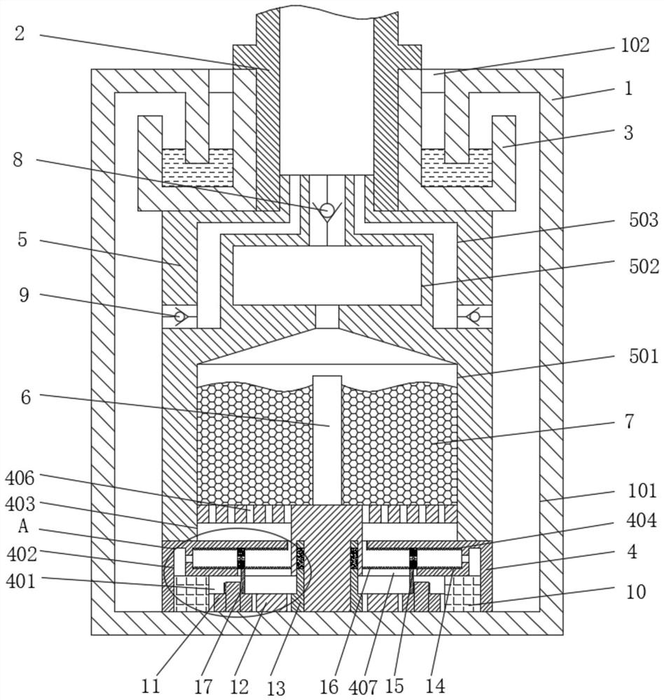
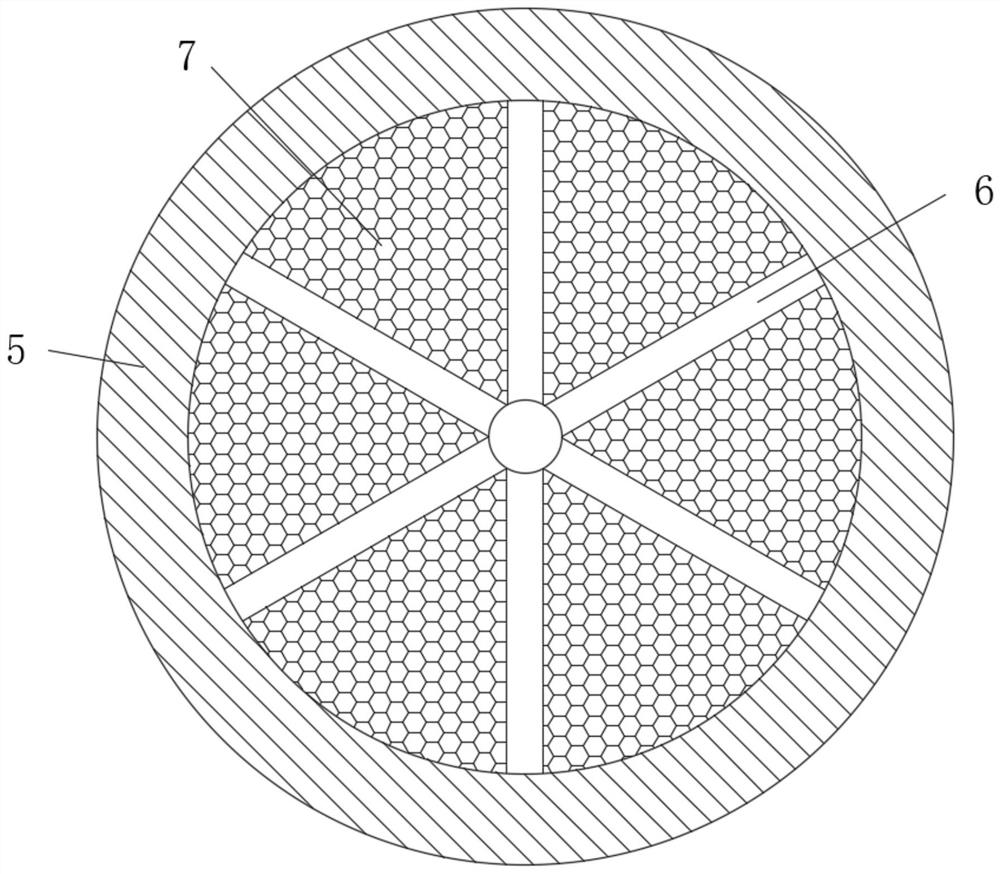
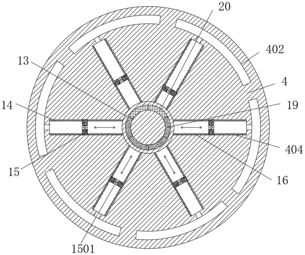
[0021] see Figure 1-5, a moisture absorber for a transformer oil conservator, comprising a glass sleeve 1 sleeved on the outer ring of the bottom of a connecting pipe 2, a ventilation cavity 101 is opened inside the glass sleeve 1, and a ring oil groove 3 is opened on the top of the ventilation cavity 101 and It is filled with transformer oil, and the transformer oil on the top can provide more space for the bottom to accommodate the air, avoiding the situati...


PUM


Abstract

The invention relates to the technical field of transformers, and discloses a moisture absorber for a transformer oil conservator. A ventilation cavity is formed in a glass sleeve, an annular oil groove is formed in the top of the ventilation cavity, transformer oil is contained in the annular oil groove, an air inlet base is fixedly installed in the middle of the ground of the ventilation cavity, and a partition plate containing silica gel is fixedly installed in a moisture absorption cavity; an air outlet hole channel communicated with the connecting pipe and the ventilation cavity is formed in the top end of moisture absorption sleeve, a movable cavity is formed in the bottom of the base, the inner ring of the movable cavity is movably sleeved with an air inlet rotating ring, air inlets are evenly formed in the outer wall of the base, and an arc-shaped air inlet arc groove is formed in the outer ring of the air inlet rotating ring; the middle of the adjusting cavity is movably sleeved with a magnetic sliding block, and one side of the adjusting cavity is fixedly provided with a second corrugated pipe with one end communicated with the separation air cavity, channels with different air inlet and outlet are formed in the glass sleeve, a base is installed at the bottom of the moisture absorption sleeve, and corresponding independent air cavities are formed in the base, so that the moisture absorption effect and quality are improved.

Description

technical field [0001] The invention relates to the technical field of transformers, in particular to a moisture absorber for a transformer oil conservator. Background technique [0002] The transformer oil in the transformer will expand with heat and contract with cold due to temperature changes, so it needs to be adjusted through the oil conservator. When adjusting, it is through suction and exhaust in the oil conservator, and the regulated air needs to be pure and dry. , so generally install a moisture absorber at the connecting pipe of the oil conservator to dry the air to ensure that the air entering the oil conservator will not affect the transformer oil, but the structure of the existing dehumidifier is simple, and there are still certain problems: [0003] 1. The existing dehumidifier is mainly composed of a glass jar filled with silica gel and a bottom cover filled with transformer oil at the bottom. When the external air enters, it needs to be removed by the transf...

Claims


Application Information

Patent Timeline
IPC IPC(8): H01F27/14
CPCH01F27/14
Inventor 郭渗渗
Owner 郭渗渗
Why Eureka
Try Eureka