Short-circuit current suppression circuit for flying capacitor converter and energy storage system with short-circuit current suppression circuit

A flying capacitor and short-circuit current technology, applied in the field of short-circuit current suppression circuits, can solve the problems of the inability to effectively disconnect the fuse of the converter, the short-circuit of other converters, and the increase of the cost of the converter, so as to reduce the short-circuit capacity requirements and suppress the short-circuit. current, the effect of improving short-circuit reliability

Pending Publication Date: 2021-10-26
DELTA ELECTRONICS (SHANGHAI) CO LTD
View PDF0 Cites 2 Cited by
  • Summary
  • Abstract
  • Description
  • Claims
  • Application Information

AI Technical Summary

Problems solved by technology

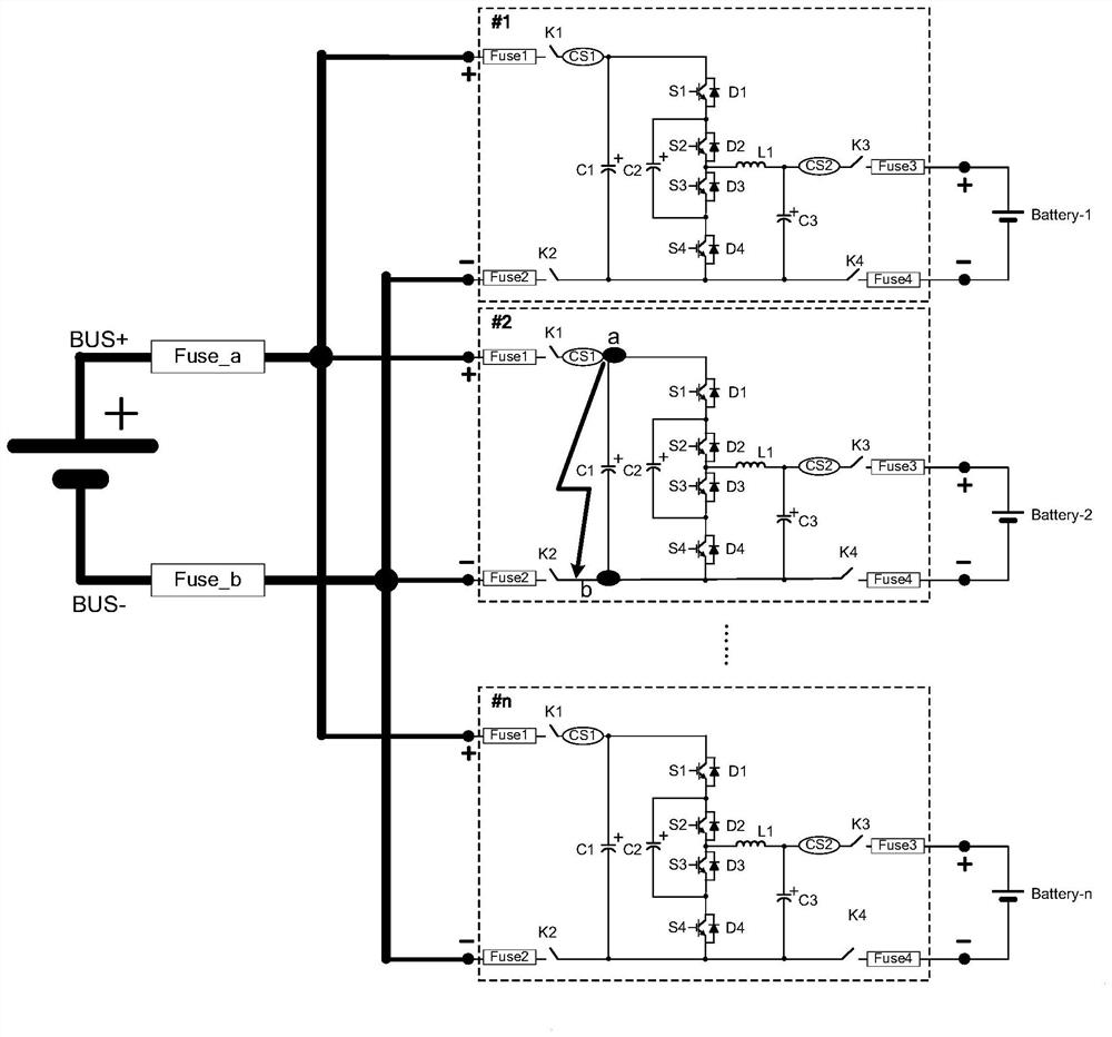
[0005] (1) The diode D1 / D2 inside the faulty converter cannot cut off the short-circuit current from the energy storage element;
[0006] (2) Cause the short circuit of the DC common bus, cause the short circuit of other converters, and cause the failure of the whole system;
[0007] (3) The short-circuit current of other converters will flow to the short-circuit point of the short-circuit faulty converter #2. For example, when the short-circuit current of each converter is 100A, if 100 converters are connected in parallel, the total current flowing through the short-circuit point The short-circuit current is 10kA, and the excessive total short-circuit current will cause the fuse of the short-circuit faulty converter to be unable to be effectively disconnected;
[0008] (4) Excessive total short-circuit current will cause overheating damage to the mechanical parts of the short-circuited faulty converter;
[0009] (5) Excessive total short-circuit current will make it difficult to select a device that meets the short-circuit capacity when designing the converter, or must select a device with a large capacity, resulting in an increase in the cost of the converter;

Method used


Image

  • Short-circuit current suppression circuit for flying capacitor converter and energy storage system with short-circuit current suppression circuit
  • Short-circuit current suppression circuit for flying capacitor converter and energy storage system with short-circuit current suppression circuit
  • Short-circuit current suppression circuit for flying capacitor converter and energy storage system with short-circuit current suppression circuit

Examples


Embodiment Construction

[0031] Example embodiments will now be described more fully with reference to the accompanying drawings. Example embodiments may, however, be embodied in many forms and should not be construed as limited to the embodiments set forth herein; rather, these embodiments are provided so that this disclosure will be thorough and complete, and will fully convey the concept of example embodiments to those skilled in the art. The same reference numerals in the drawings denote the same or similar structures, and thus their detailed descriptions will be omitted.

[0032] When introducing elements / components / etc. described and / or illustrated herein, the terms "a", "an", "the", "said" and "at least one" are used to mean that there are one or more elements / components / etc. The terms "comprising", "including" and "having" are used in an open inclusive sense and mean that there may be additional elements / components / etc. besides the listed elements / components / etc. Relative terms such as "up...


PUM


Abstract

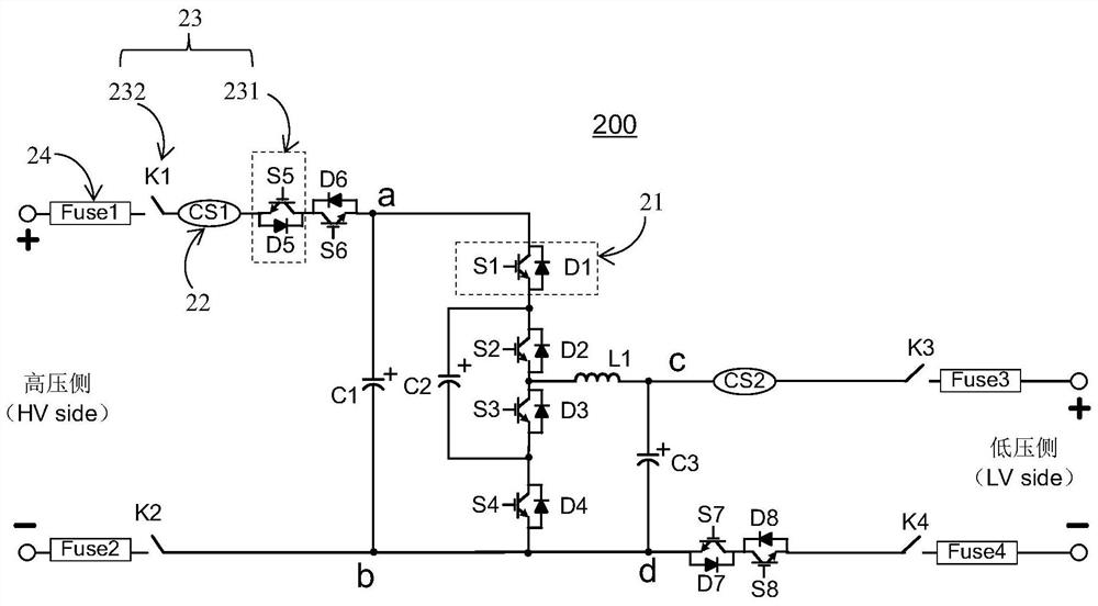
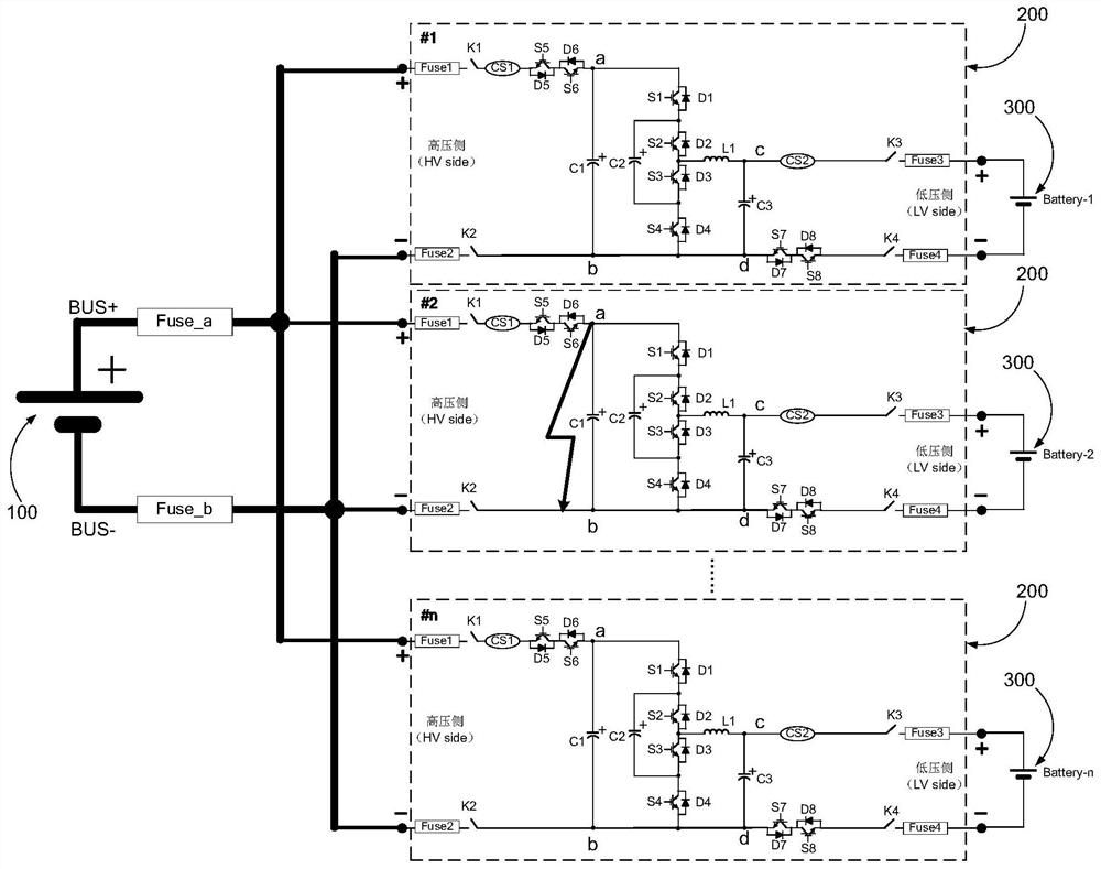
The invention discloses a flying capacitor converter and a short-circuit current suppression circuit and an energy storage system used for the flying capacitor converter. The flying capacitor converter comprises a controller, the high-voltage side of the flying capacitor converter being connected with a first power supply, the low-voltage side of the flying capacitor converter being connected with a second power supply. The short-circuit current suppression circuit comprises at least one current detection component connected to the low-voltage side and / or the high-voltage side of the flying capacitor converter; and at least a switch assembly, connected to the high-voltage side and / or the low-voltage side of the flying capacitor converter in series, and when the current detection component detects a short circuit condition, the controller controlling the switch assembly to disconnect the flying capacitor converter and the first power supply and / or the flying capacitor converter and the second power supply. According to the invention, the short-circuit current of the flying capacitor converter can be rapidly suppressed, the short-circuit capacity of the converter is reduced, and the short-circuit reliability of an energy storage system composed of a plurality of flying capacitor converters can be improved.

Description

technical field [0001] The present invention relates to a short-circuit current suppression circuit, in particular to a short-circuit current suppression circuit for a flying capacitor converter, a flying capacitor converter with the short-circuit current suppression circuit, and a flying capacitor converter with the energy storage system. Background technique [0002] At present, flying capacitor converters have begun to be used in energy storage systems, such as figure 1 As shown, multiple flying capacitor converters (such as figure 1 One end of converter #1, converter #2, ..., converter #n and other n converters) is connected to the DC grid or DC common bus, and the other end is connected to the energy storage element, such as super Capacitors or batteries (such as figure 1 There are n batteries such as Battery-1, Battery-2, ..., Battery-n shown in ). [0003] In practical applications, multiple flying capacitor converters are connected to the DC common bus to charge ...

Claims


Application Information

Patent Timeline
Patent Type & Authority Applications(China)
IPC IPC(8): H02H7/12H02H3/08H02M1/32H02J7/34
CPCH02H7/1213H02H3/08H02M1/32H02J7/34H02J7/345H02M1/008H02M3/158H02M3/07H02M1/0095H01H71/123H02H3/087H02M1/0009
Inventor 周玉虎陈海东沈国桥章进法
Owner DELTA ELECTRONICS (SHANGHAI) CO LTD
Why Eureka
Try Eureka