
A device for automatically limiting short-circuit fault current in AC grid

A technology for short-circuit faults and AC power grids, which is applied to emergency protection circuit devices, circuit devices, emergency protection circuit devices, etc. for limiting overcurrent/overvoltage, and can solve the problem of circuit breaker explosion, high operation and maintenance costs, and difficulty in popularization, etc. problem, to achieve the effect of ensuring the safety of operation

Active Publication Date: 2018-01-09
章则明 +1
View PDF4 Cites 0 Cited by
  • Summary
  • Abstract
  • Description
  • Claims
  • Application Information

AI Technical Summary

Problems solved by technology

[0007] 1. The greater the current limiting effect of fixed impedance and semiconductor components, the greater the loss ratio during normal operation;
[0008] 2. The superconducting current limiter has a good current limiting effect, but it needs an ultra-low temperature operating environment, the equipment investment is nearly 100 million yuan and the operation and maintenance costs are high, so it is difficult to promote in engineering
[0009] 3. After searching by the applicant, the patent of the same type, such as the authorized announcement number CN103023000B of the Electric Power Science Academy of Ningxia Electric Power Company, has the problem that the high-speed switch and the current-limiting reactor are usually operated in parallel. When the short-circuit current occurs, the following The electrical protection device needs to disconnect the high-speed switch first, and then the current-limiting reactor can be connected in series to play the role of current limiting, but the actual situation is that any high-speed switch is within the first half-wave time of the first cycle of the short-circuit moment of the AC circuit. Within seconds (10ms), according to the switch arc theory, it is impossible to completely eliminate the arc in the arc extinguishing chamber, but the arc can only be extinguished after the zero-crossing point of the first cycle, that is, 10ms (milliseconds), which means After 10ms, the above reactance current limiter can be effectively put into work
In the actual situation of the power grid, the first cycle (that is, within 0-10ms) after the short circuit is the most urgent to limit the short-circuit current value, because the circuit breaker at the lower end of the current-limiting reactor may have activated at this time, if it waits for 15ms If the current limiter is put in later, the circuit breaker at the lower end may not be able to extinguish the arc due to the insufficient breaking capacity of the arc extinguishing chamber, so that the arc is always in a burning state, so that the circuit cannot be broken or the circuit breaker will explode.

Method used


Image

  • A device for automatically limiting short-circuit fault current in AC grid
  • A device for automatically limiting short-circuit fault current in AC grid
  • A device for automatically limiting short-circuit fault current in AC grid

Examples


Embodiment 1

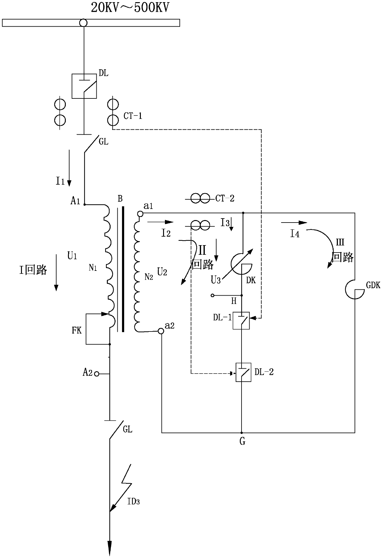
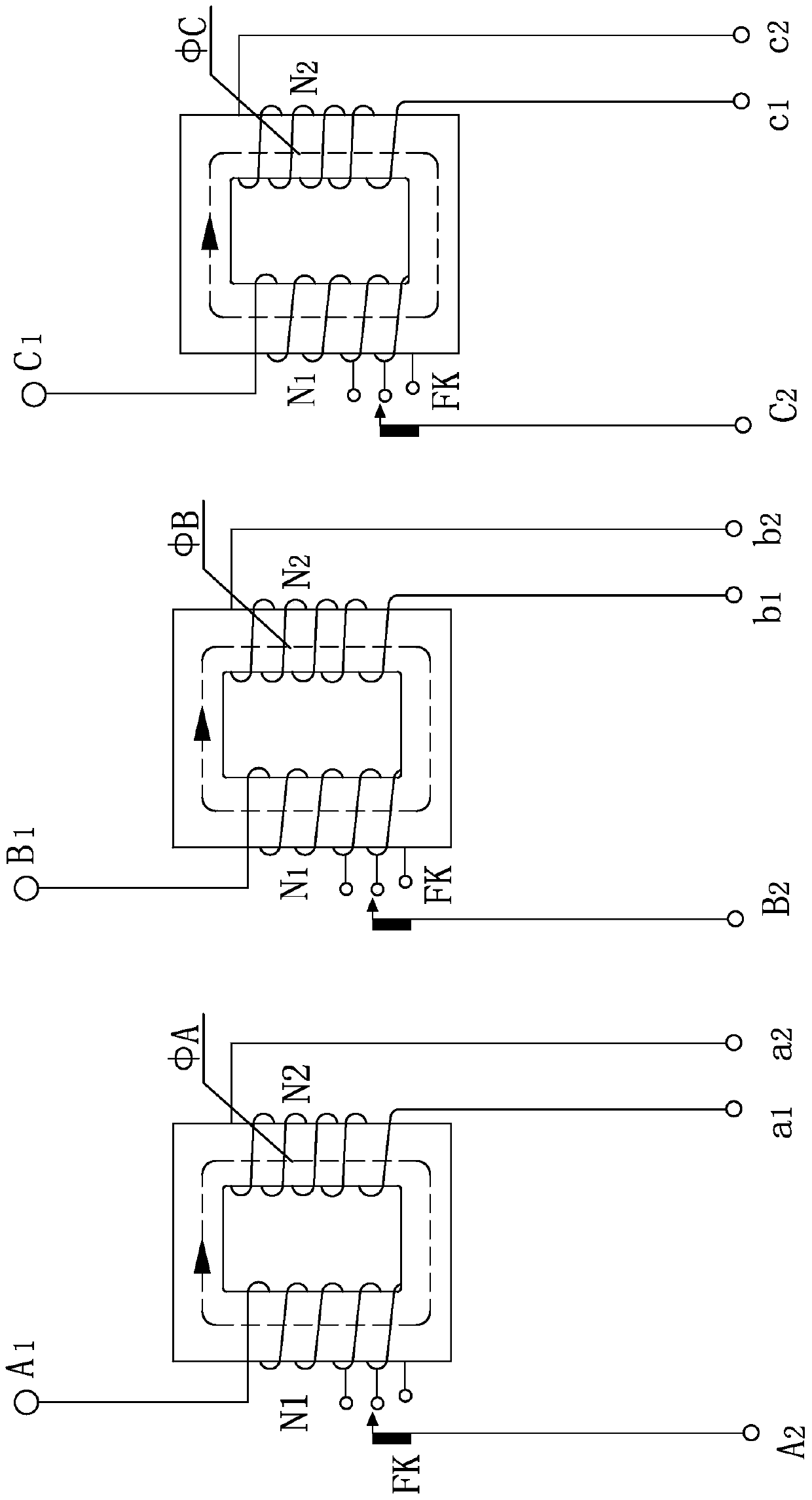
[0036] Embodiment one, such as figure 1 , Figure 3-6 As shown, the device for automatically limiting the short-circuit fault current is applied to the AC power grid with a rated voltage level of 500KV. The feeder circuit breaker DL, the feeder current transformer CT-1, the incoming line side isolating switch GL and the Outlet side isolating switch GL, this device (variable reactance current limiter) is connected in series between two isolating switches GL, said variable reactance current limiter consists of iron core body, primary winding N 1 and the secondary winding N 2 Composed of main reactor B, air gap reactor DK, main circuit breaker DL-1 (in this example, sulfur hexafluoride high-voltage circuit breaker) and high-resistance reactor GDK (in this example, a reactor with high impedance and air gap, Its reactance resistance value is 10 to 20 times the upper limit value of the air gap reactor DK). where the primary winding N 1 Connected in series in the feeder, it is th...

Embodiment 2

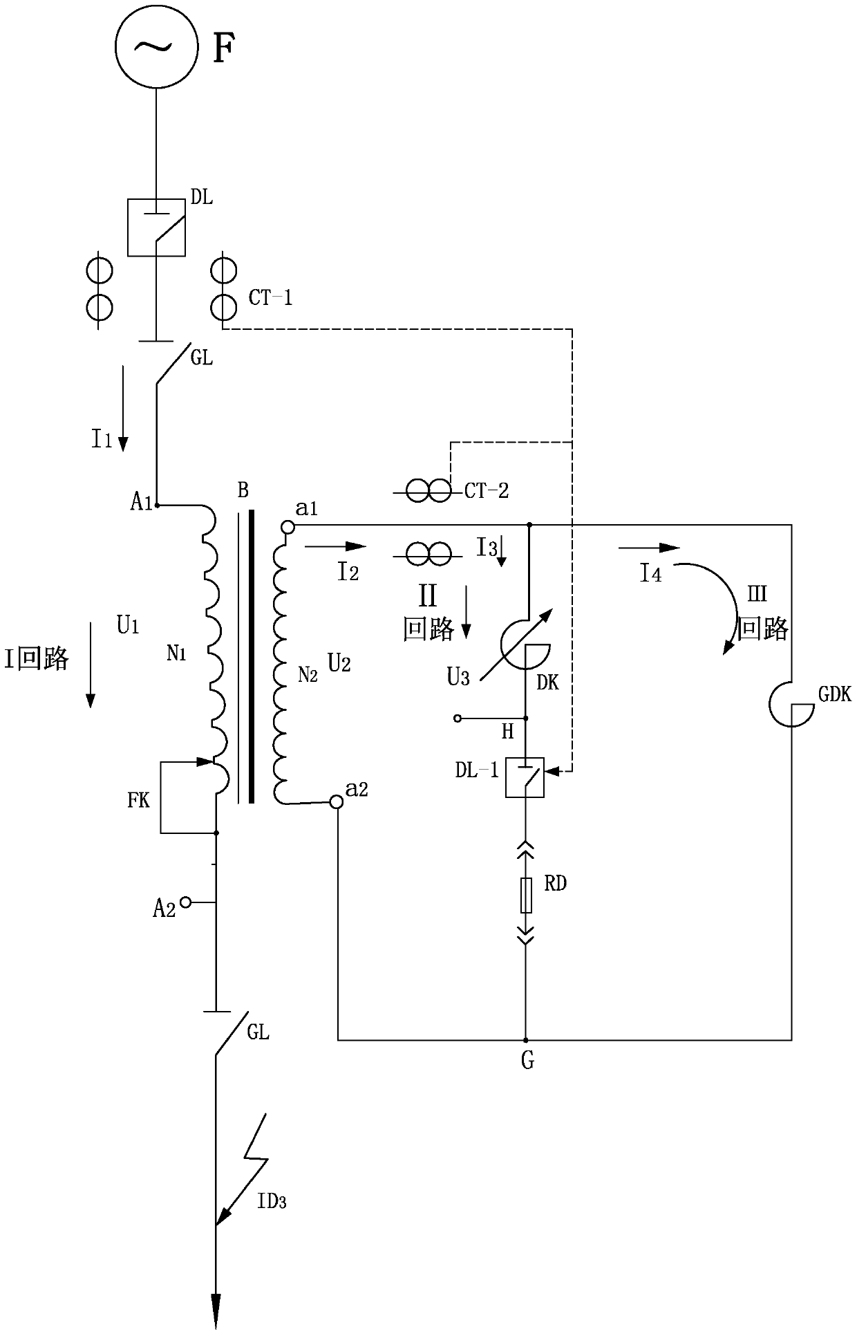
[0048] Embodiment two, such as figure 2 , Figure 3-6 As shown, the basic structure of this embodiment is the same as that of Example 1, the only difference is that the backup circuit breaker DL-2 is replaced by the fast fuse RD; this device is applied to the short-circuit protection of a 600,000-kilowatt large-scale generating set.


PUM


Abstract

The invention relates to a device for automatically restricting short circuit fault current in an alternating current power grid. The invention aims to cause the device to be under low-power loss when the device normally operates, can increase the reactance value number of an electric reactor while a circuit is subjected to short circuit, and lightens the damage degree of a short circuit fault. The device is provided with a 20-500KV alternating current bus; a power transmission feeder is successively connected with a feeder circuit breaker, a feeder current mutual inductor and two disconnecting switches; a variable reactance current limiter is connected between the two disconnecting switches of the feeder; the variable reactance current limiter comprises a main electric reactor, an air gap electric reactor, a main circuit breaker and high-resistance reactors, wherein the main electric reactor consists of an iron core body, a primary winding and a secondary winding; the primary winding is connected in the feeder in series and is a first loop; the secondary winding, the air gap electric reactor and the main circuit breaker form a second loop; the high-resistance reactors connected to two ends of the secondary winding in parallel form a third loop; and meanwhile, the feeder current mutual inductor, a secondary winding side current mutual inductor and a relay protection control system installed in a power substation form a detection control loop.

Description

technical field [0001] The invention relates to a device for automatically limiting short-circuit fault current in an AC network. Prevent the high-voltage electrical equipment in the grid from being destroyed due to short-circuit faults. Background technique [0002] At present, with the increasing scale of my country's power grid and the rapid growth of loads in the power system, especially at the end of 2014, my country's installed power generation capacity has reached 1.25 billion kilowatts, ranking first in the world. So many large-capacity units have been put into operation And the interconnection of power grids in various regions makes the short-circuit current level of the power system increase day by day. The short-circuit current level of power grids in many areas, especially coastal economically developed areas such as Shanghai, Jiangsu, Zhejiang, and Guangdong, has reached or even exceeded the limit of the "Electric Power Regulations" the maximum allowable value of...

Claims


Application Information

Patent Timeline
Patent Type & Authority Patents(China)
IPC IPC(8): H02H9/02H02H7/06H01F29/10
CPCH01F30/06H02H7/06H02H9/02
Inventor 张健张京伦
Owner 章则明
Learn More