
Intelligent temperature control system based on communication network engineering

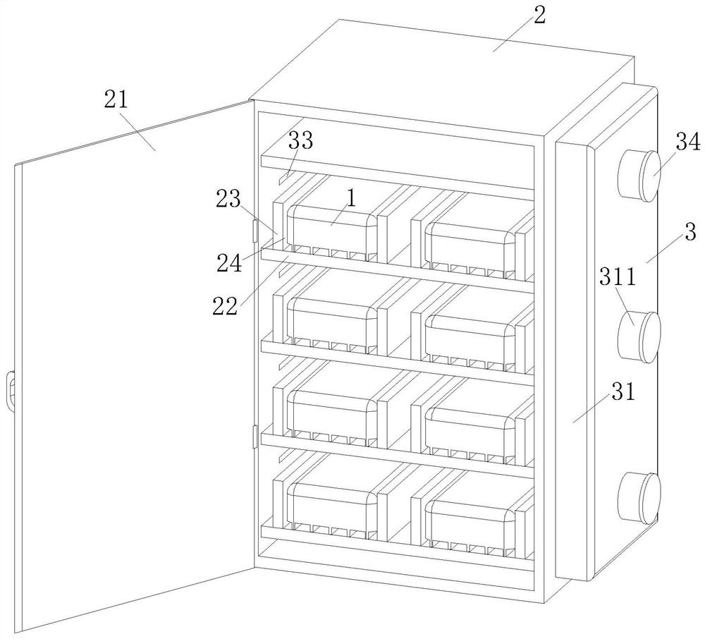
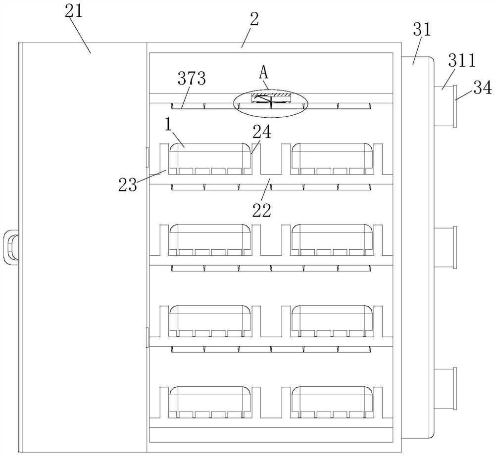
A technology of communication network and intelligent temperature control, which is applied in the direction of control/regulation system, temperature control, non-electric variable control, etc. It can solve the problems affecting the communication server line and the large load of the drive device, so as to achieve centralized and effective effect, prevent spread, Avoid the effects of loss of weakening

Active Publication Date: 2021-10-26
陕西赢轲徕网络科技有限公司
View PDF11 Cites 0 Cited by
  • Summary
  • Abstract
  • Description
  • Claims
  • Application Information

AI Technical Summary

Problems solved by technology

[0005] In order to make up for the deficiencies of the existing technology, the existing intelligent temperature control system drives the communication server to move through the driving device, so that the communication server is subjected to centralized cooling, which may easily cause excessive load on the driving device and affect the lines connected to the communication server; the present invention proposes An intelligent temperature control system based on communication network engineering

Method used


Image

  • Intelligent temperature control system based on communication network engineering
  • Intelligent temperature control system based on communication network engineering
  • Intelligent temperature control system based on communication network engineering

Examples


Embodiment approach

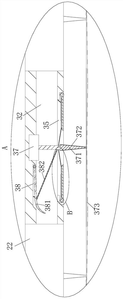
[0032] As a specific embodiment of the present invention, the No. 1 plate 36 includes a flow guide plate 362 and a windshield 363, the windshield 363 is rotatably connected to the side wall of the cooling groove 35, and the upper surface of the windshield 363 is provided with a There is a chute 364, on which a drainage plate 362 is nested, one end of the drainage plate 362 is connected to the inner surface of the chute 364 through a reset elastic rope, and the other end is connected to the end of the expansion rod 37 through a No. 1 elastic rope 361 connected.

[0033] During work, when the telescopic rod 37 was not started, the diversion plate 362 on the No. 1 board 36 was positioned at the inside of the chute 364 on the windshield 363, and the diversion plate 362 and the windshield 363 kept overlapping; The end of the rod 37 pulls the diversion plate 362 through the No. 1 elastic rope 361, so that the end of the diversion plate 362 is stressed and rotates downward; The chut...


PUM


Abstract

The invention belongs to the technical field of temperature control systems, and particularly relates to an intelligent temperature control system based on communication network engineering, the intelligent temperature control system comprises a communication unit, a protection unit and an intelligent temperature control unit, the communication unit comprises a server body, and the server body is used for providing service support for a user of a communication network; the protection unit comprises a cabinet, a cabinet door and a partition plate; according to the invention, by starting the telescopic rod above the cooling groove right facing the overheated part, the air quantity passing through the cooling groove is increased, and cooling air intensively flows to the overheated part on the server body through the gap between the first plates, so that the overheated part is cooled in a centralized manner; and when the server body is on fire, the carbon dioxide gas tank is started to spray carbon dioxide gas to act on the on-fire part in a centralized manner through the cooling tank, so that the on-fire part is prevented from spreading.

Description

technical field [0001] The invention belongs to the technical field of temperature control systems, in particular to an intelligent temperature control system based on communication network engineering. Background technique [0002] Under the premise that the power consumption of electronic components in the cabinet is rising sharply, one of the important prerequisites for how to keep the electronic components in the cabinet in a stable operating state is that the thermal control of the internal and external environments of the cabinet reaches a stable state; therefore, the cabinet The reliability of the temperature control system in the inner cavity space and the intelligence of the temperature control process will also greatly affect the strengthening and exertion of the functions of the communication cabinet. Therefore, how to solve various failures and hidden dangers caused by unstable heat management of cabinets, big data centers and servers in a reliable, efficient and...

Claims


Application Information

Patent Timeline
Patent Type & Authority Applications(China)
IPC IPC(8): H05K5/02H05K7/14H05K7/20G05D23/20
CPCH05K5/0217H05K5/0247H05K7/14H05K7/20136H05K7/20509H05K7/20145G05D23/20
Inventor 秦本兵朱述勇
Owner 陕西赢轲徕网络科技有限公司
Learn More