Decoding apparatus and decoding method
A decoding device and decoding method technology, applied in other decoding technologies, coding, code conversion and other directions, can solve the problem of time required for decoding processing, and achieve the effect of suppressing the total amount
- Summary
- Abstract
- Description
- Claims
- Application Information
AI Technical Summary
Problems solved by technology
Method used
Image

Examples
Embodiment approach 1
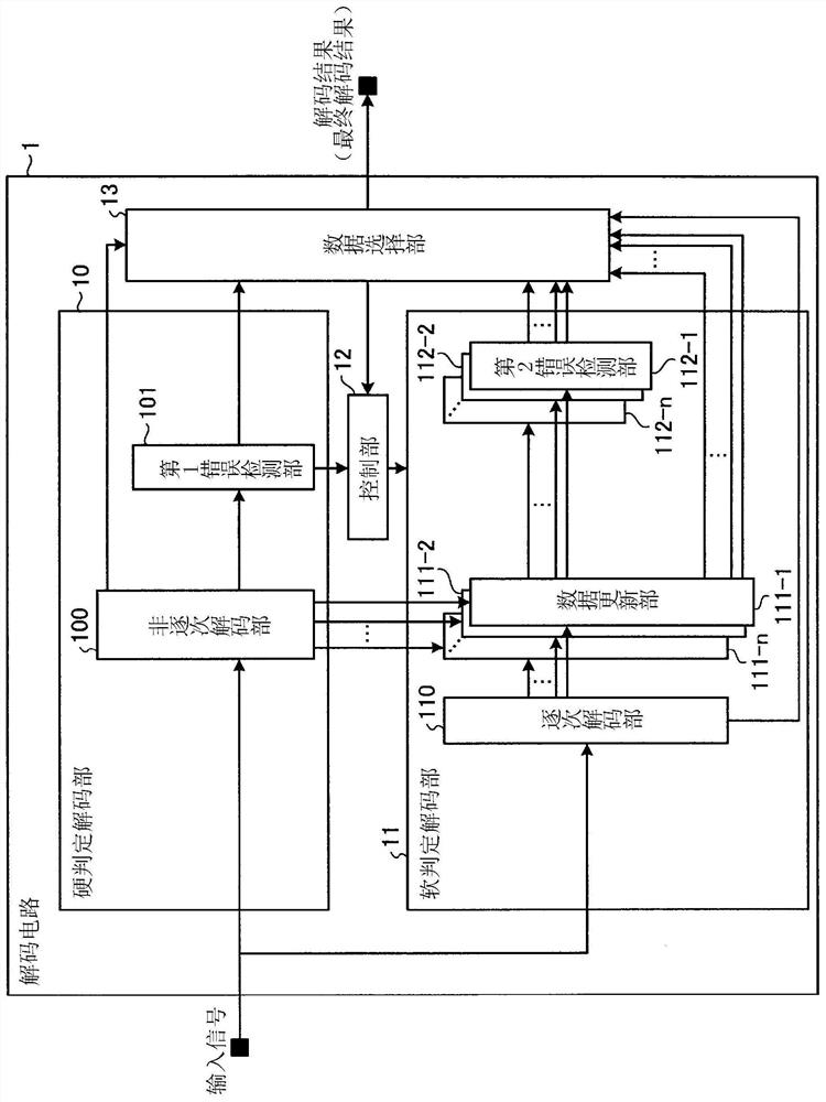
[0027] figure 1 It is a diagram showing a configuration example of a decoding circuit according to Embodiment 1 of the present invention. figure 1 The shown decoding circuit 1 is an example of the decoding device of the present invention. The decoding circuit 1 decodes an input signal, and outputs the decoding result to a subsequent circuit not shown. In addition, as will be described later, the decoding circuit 1 also calculates a decoding result which is an intermediate result during successive decoding. The decoding result which is an intermediate result and the decoding result output to the subsequent stage circuit are both decoding results, and the decoding result output to the subsequent stage circuit is referred to as the final decoding result hereinafter. For example, when the decoding circuit 1 adds redundant bits to output the decoding result, the latter circuit is a circuit for eliminating redundant bits, and when applying a concatenated code that performs error c...
Embodiment approach 2
[0072] Image 6 It is a diagram showing a configuration example of a decoding circuit according to Embodiment 2 of the present invention. Such as Image 6 As shown, the decoding circuit 2 is an example of the decoding device of the present invention. Like the decoding circuit 1 of Embodiment 1, the decoding circuit 2 decodes the input signal, and outputs the decoding result to a subsequent circuit not shown. In addition, in this embodiment, the decoding result output to the subsequent stage circuit is also referred to as the final decoding result. Hereinafter, overlapping descriptions of the same parts as those in Embodiment 1 will be omitted, and the parts different from Embodiment 1 will be mainly described.
[0073] In the present embodiment, coding of a systematic polar code to which redundant bits are added for performing error detection in a transmission device is performed. A systematic polar code is a polar code capable of separating information bits and redundant ...
Embodiment approach 3
[0102] Figure 8 It is a diagram showing a configuration example of a decoding circuit according to Embodiment 3 of the present invention. The present embodiment implements encoding of a systematic polar code to which redundant bits are added to perform error detection in a transmission signal. Such as Figure 8 As shown, the decoding circuit 3 is an example of the decoding device of the present invention. Like the decoding circuits 1 and 2 of the first and second embodiments, the decoding circuit 3 decodes the input signal, and outputs the decoding result to a subsequent circuit not shown. In addition, in this embodiment, the decoding result output to the subsequent stage circuit is also referred to as the final decoding result. The input signal of this embodiment is the same as that of Embodiment 2. Hereinafter, overlapping descriptions of the same parts as those in Embodiment 2 will be omitted, and the parts different from Embodiment 2 will be mainly described.
[0103...
PUM
 Abstract
Description
Claims
Application Information
 - R&D
- Intellectual Property
- Life Sciences
- Materials
- Tech Scout
- Unparalleled Data Quality
- Higher Quality Content
- 60% Fewer Hallucinations
Browse by: Latest US Patents, China's latest patents, Technical Efficacy Thesaurus, Application Domain, Technology Topic, Popular Technical Reports.
© 2025 PatSnap. All rights reserved.Legal|Privacy policy|Modern Slavery Act Transparency Statement|Sitemap|About US| Contact US: help@patsnap.com