Check patentability & draft patents in minutes with Patsnap Eureka AI!

Inverter Control

A control device and inverter technology, applied in control systems, motor control, AC motor control, etc., can solve the problems of component cost, manufacturing cost, product cost impact, life reduction, power consumption, etc.

Active Publication Date: 2018-10-23
AISIN AW CO LTD
View PDF4 Cites 0 Cited by
  • Summary
  • Abstract
  • Description
  • Claims
  • Application Information

AI Technical Summary

Problems solved by technology

In ASC control, although the rise of the DC link voltage can be suppressed, a large current (circulating current) flows into the switching element and the stator coil
In addition, a large current continues to flow until the electric power accumulated in the stator coil due to heat etc. is consumed
Therefore, there is a possibility that the switching element and the stator coil are consumed, and the service life may be shortened.
In addition, it is necessary to use switching elements corresponding to large currents, which may also affect component costs, manufacturing costs, and product costs.

Method used


Image

  • Inverter Control
  • Inverter Control
  • Inverter Control

Examples


Embodiment Construction

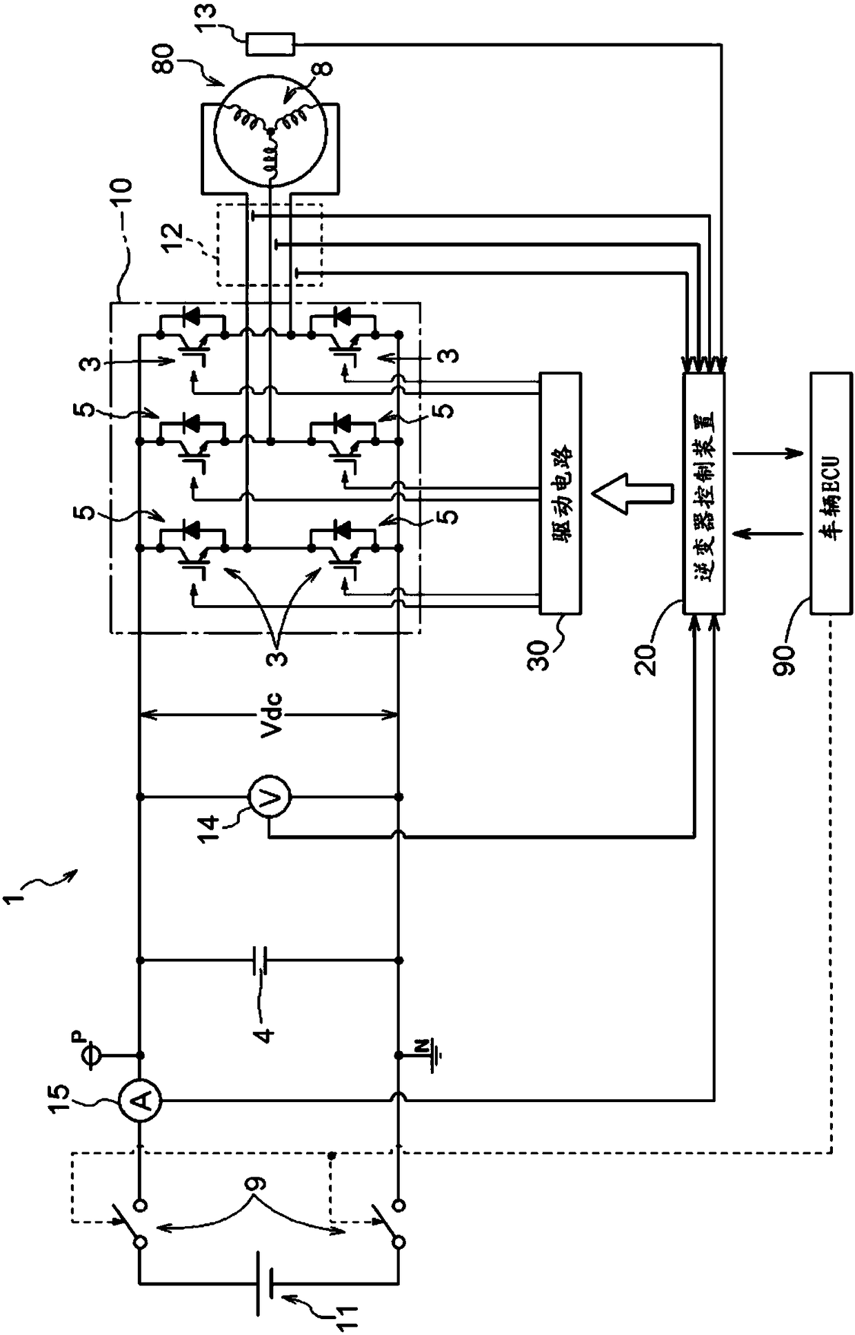
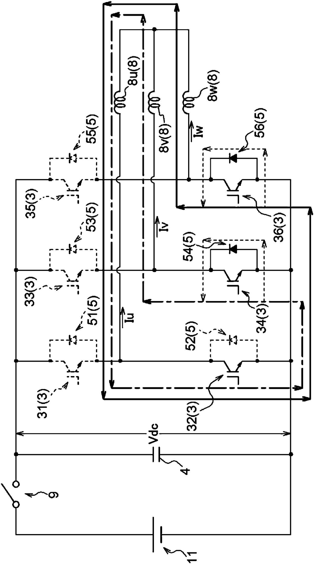
[0023] Hereinafter, embodiments of the inverter control device will be described based on the drawings. Such as figure 1 As shown, the inverter control device 20 takes the rotating electric machine driving device 1 including the inverter 10 and the DC link capacitor 4 as a control object, and drives and controls the rotating electric machine 80 via the rotating electric machine driving device 1 . As will be described later, the inverter 10 is connected to a DC power supply (11) via a contactor 9, and is connected to an AC rotating electrical machine 80, and performs electric power between DC and multi-phase AC (here, 3-phase AC). In the power conversion device for conversion, the arm of the AC 1-phase is constituted by a series circuit of an upper-stage side switching element and a lower-stage side switching element. The DC link capacitor 4 smoothes the DC link voltage Vdc which is the voltage on the DC side of the inverter 10 . The rotating electric machine 80 to be driven...


PUM


Abstract

The present invention suppresses an increase in the DC link voltage of the inverter and the total amount of circulating current when the contactor connecting the inverter and the DC power supply is in a released state. When the contactor (9) is in the released state during the rotation of the rotating electric machine, the inverter control device executes to set the switching element (34) controlled to be in the conductive state in an arm of any one phase, that is, the target arm. Partial turn-off control is performed to control the off state, and then, when the currents (Iu, Iw) of the other two-phase arms are all zero, all remaining switching elements (3 ) is set to the cut-off state to control the full-close control.

Description

technical field [0001] The present invention relates to the technology of driving and controlling an alternating current rotating electric machine. Background technique [0002] For example, a large-output AC rotating electrical machine used for powering an electric vehicle, a hybrid vehicle, etc. is driven at a relatively high voltage. In addition, since the high-voltage power source mounted on such an automobile is a DC battery, it is converted to, for example, a 3-phase AC by an inverter circuit using a switching element. The rotating electrical machine functions not only as a motor that outputs power to drive a vehicle using electric energy, but also as a generator that generates electricity using kinetic energy of a vehicle, an internal combustion engine, or the like. The electric power generated by the rotating electric machine is regenerated and accumulated in the battery. [0003] However, there are cases where a switching device (contactor) is provided between the...

Claims


Application Information

Patent Timeline
Patent Type & Authority Patents(China)
IPC IPC(8): H02M1/32H02M1/36H02M7/5387
CPCH02M1/32H02M1/36H02M7/5387H02P27/06H02P29/0241B60L50/51Y02T10/70H02P6/14H02P29/024
Inventor 苏布拉塔·萨哈岛田有礼
Owner AISIN AW CO LTD
Features
  • R&D
  • Intellectual Property
  • Life Sciences
  • Materials
  • Tech Scout
  • Unparalleled Data Quality
  • Higher Quality Content
  • 60% Fewer Hallucinations
Learn More