
Optical coupler, beam splitter, and arrayed waveguide grating type optical wavelength division multiplexer

Inactive Publication Date: 2005-06-23
NEC CORP
View PDF10 Cites 11 Cited by
  • Summary
  • Abstract
  • Description
  • Claims
  • Application Information

AI Technical Summary

Benefits of technology

[0014] According to the present invention there are provided an optical coupler, a beam splitter, and an AWG, which are provided with a transition region for attaining a low loss and which can effectively prevent the reflection of optical signals occurring in the transition region.
[0016] Thus, the optical coupler according to the present invention is provided with waveguide paths for connecting adjacent output waveguides through which optical signals are outputted. The waveguide paths are arranged in such a manner that the waveguide paths positioned on the right and left sides of each of the output waveguides are different in their distances from the slab waveguide. Consequently, in each output waveguide, a rise in equivalent refractive index caused by an arrangement of the waveguide paths is decreased and reflection becomes difficult to occur.
[0018] Thus, the beam splitter according to the present invention is provided with waveguide paths for connecting adjacent output waveguides through which optical signals are outputted. The waveguide paths are arranged in such a manner that the waveguide paths positioned on the right and left sides of each of the output waveguides are different in their distances from the input waveguide. Consequently, in each output waveguide, a rise in equivalent refractive index caused by an arrangement of the waveguide paths is decreased and reflection becomes difficult to occur.
[0020] Thus, the arrayed waveguide grating type optical wavelength division multiplexer according to the present invention is provided with waveguide paths for connecting adjacent ones of arrayed waveguides in which optical signals are outputted from the first slab waveguide. The waveguide paths are arranged in such a manner that the waveguide paths positioned on the right and left sides of each output waveguide are mutually different in their distances from the first or the second slab waveguide. Consequently, in each output waveguide, a rise in equivalent refractive index caused by an arrangement of the waveguide paths is decreased and reflection becomes difficult to occur.

Problems solved by technology

Consequently, in each output waveguide, a rise in equivalent refractive index caused by an arrangement of the waveguide paths is decreased and reflection becomes difficult to occur.

Method used


Image

  • Optical coupler, beam splitter, and arrayed waveguide grating type optical wavelength division multiplexer
  • Optical coupler, beam splitter, and arrayed waveguide grating type optical wavelength division multiplexer
  • Optical coupler, beam splitter, and arrayed waveguide grating type optical wavelength division multiplexer

Examples


first embodiment

[0048] First, a description will be given of a basic construction of an AWG (Arrayed Waveguide Grating type optical wavelength division multiplexer) according to the present invention.

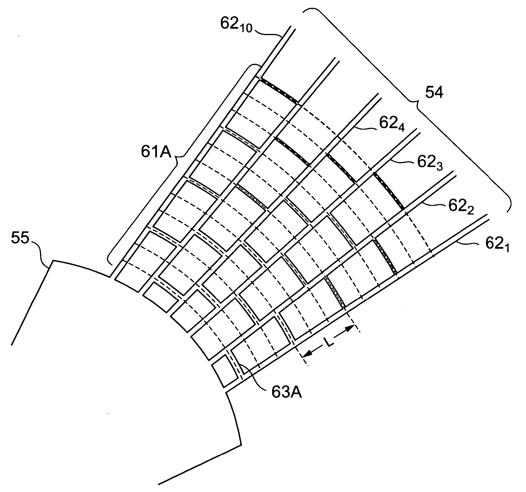
[0049]FIG. 4 shows an outline of the AWG of the first embodiment. One or more first channel waveguides 52, plural second channel waveguides 53, and arrayed waveguides 54 which are bent in certain directions at different radii of curvature, are arranged on a substrate 51 as a constituent of the AWG 50. A first slab waveguide 55 for connection between the first channel waveguide 52 and the arrayed waveguides 54, as well as a second slab waveguide 56 for connection between the arrayed waveguide 54 and the second channel waveguides 53, are also arranged on the substrate 51. A transition region 61 for gently changing the state of connection is provided near one or both of the first and second slab waveguides 55, 56. A certain optical path length difference (waveguide length difference) AL is provided betwee...


PUM


Abstract

An optical coupler, a beam splitter, and an AWG, according to the present invention are each provided with a transition region for the attainment of a low loss and can effectively prevent the reflection of optical signals which occurs in the transition region. The optical coupler, beam splitter, and AWG, according to the present invention are each provided with a slab waveguide 55, plural waveguides 621, 622, . . . , 6210 for the output of optical signals and further provided with plural waveguide paths 63 for connecting adjacent ones of the waveguides 621, 622, . . . , 6210. The waveguide paths 63 adjacent with respect to each of the waveguides are positioned at different distances from the slab waveguide 55.

Description

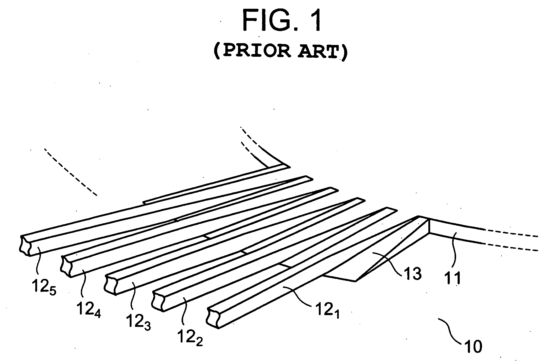
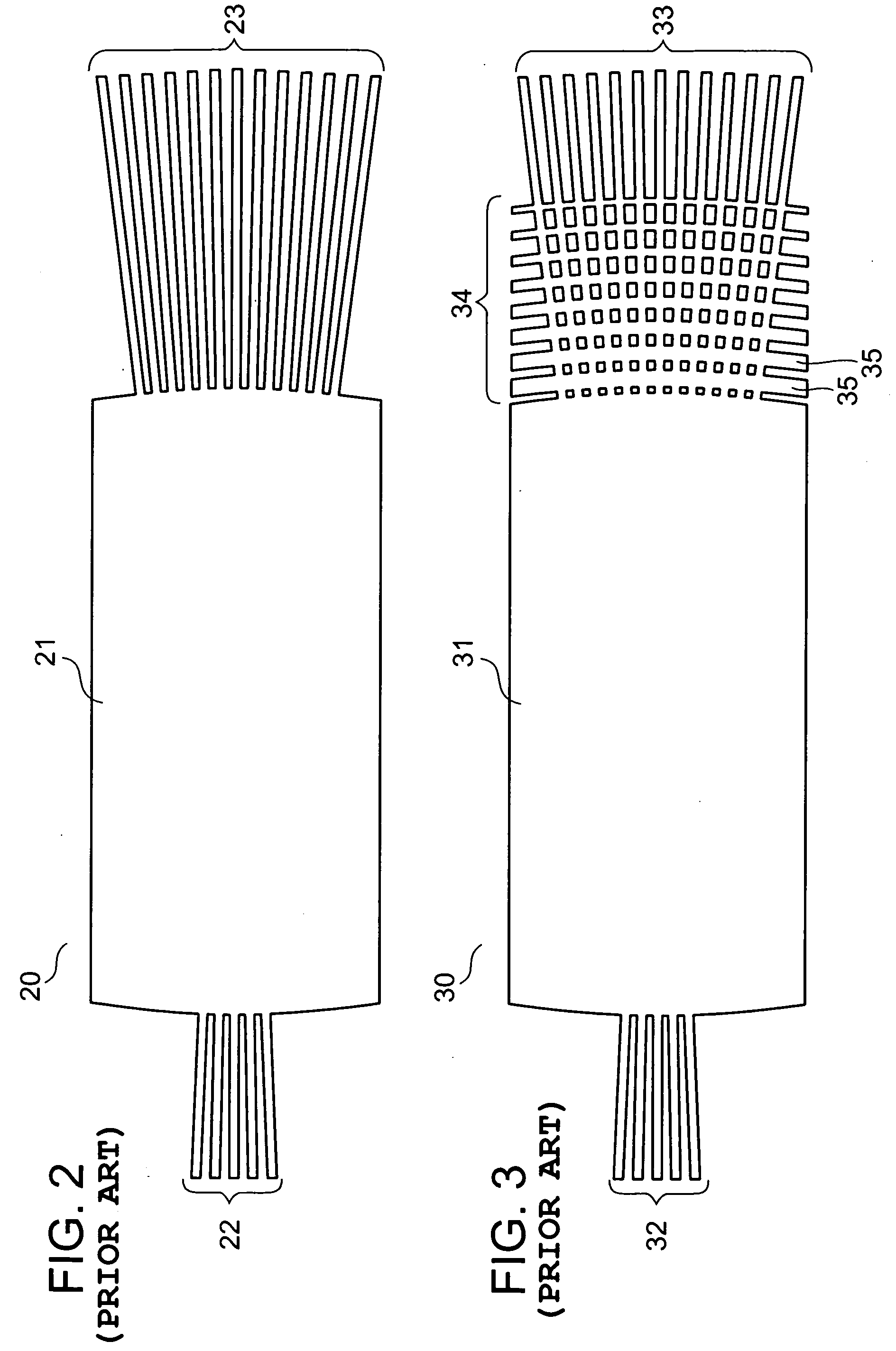
BACKGROUND OF THE INVENTION [0001] 1. Field of the Invention [0002] The present invention relates to an optical coupler for branching or coupling optical signals, a beam splitter for branching optical signals, and an AWG (Arrayed Waveguide Grating type optical wavelength division multiplexer) for combining or branching optical signals. Particularly, the present invention is concerned with an optical coupler, a beam splitter, and an AWG, of a low loss type. [0003] 2. Description of Related Art [0004] With an increase of the information transmission volume, a WDM (Wavelength Division Multiplexing) transmission system capable of remarkably increasing the transmission capacity is in wide commercial use. In this WDM transmission system, optical signals of plural wavelengths are transmitted using a single optical fiber. Therefore, optical wavelength division multiplexers are needed at input and output portions of the optical fiber which serves as a transmission path. The optical wavelengt...

Claims


Application Information

Patent Timeline
IPC IPC(8): G02B6/12G02B6/34
CPCG02B6/12011G02B6/12007
Inventor YAMAZAKI, HIROYUKI
Owner NEC CORP
Learn More