
Screw compressor

a compressor and screw technology, applied in the direction of machines/engines, rotary/oscillating piston pump components, liquid fuel engines, etc., can solve the problems of disadvantageous increase of sliding resistance on the contact surface of the compressor, and achieve the effect of improving lubrication characteristics, reducing leakage, and increasing lubrication area

Active Publication Date: 2014-01-09
DAIKIN IND LTD
View PDF2 Cites 10 Cited by
  • Summary
  • Abstract
  • Description
  • Claims
  • Application Information

AI Technical Summary

Benefits of technology

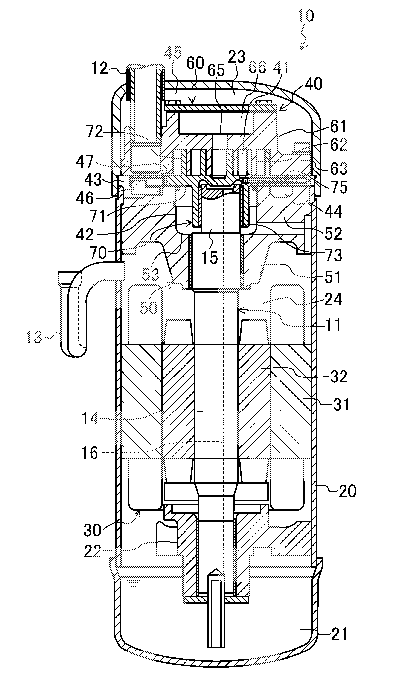
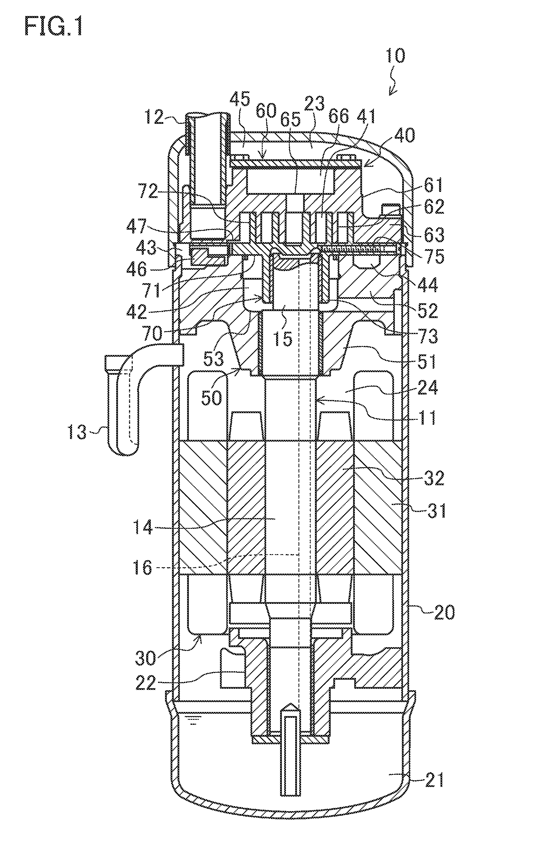
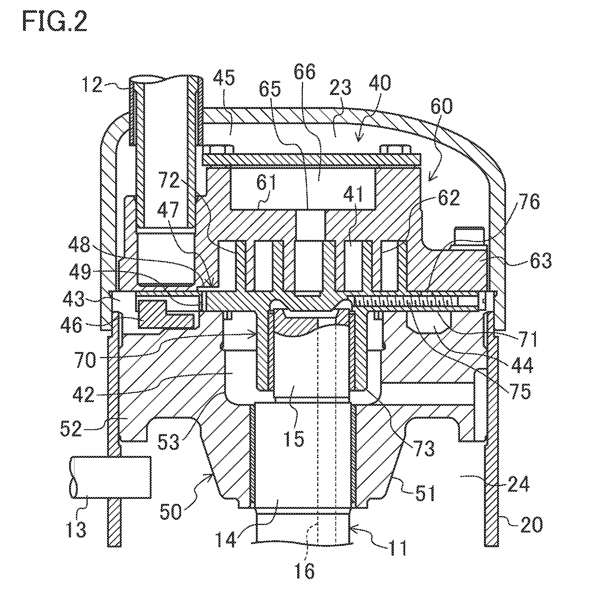
The present invention provides a scroll compressor with improved lubrication and reduced oil leakage. It achieves this by designing an oil groove on the end plate of the orbiting scroll that communicates with an oil groove on the fixed scroll, increasing the lubrication area on the thrust surface. The oil groove on the orbiting scroll extends from the end of the oil groove on the fixed scroll along the periphery of the end plate, further increasing lubrication area. This configuration allows for a fixed amount of lubricating oil to be supplied to the thrust surface, preventing excessive supply and reducing oil temperature. The oil groove on the orbiting scroll also supplies lubrication to the sliding areas in the compression pockets, ensuring proper lubrication and reducing oil accumulation there. Overall, this design improves the efficiency and reliability of the scroll compressor.

Problems solved by technology

Such a scroll compressor disadvantageously increases sliding resistance on a contact surface between the fixed scroll and the orbiting scroll.

Method used


Image

  • Screw compressor
  • Screw compressor
  • Screw compressor

Examples


embodiment

Alternative Example of Embodiment

[0072]FIGS. 7 and 8 illustrate an alternative example of an oil groove (83) on an orbiting scroll of a scroll compressor (10). In this alternative example, similarly to the above-described embodiment, the oil groove (83), on the orbiting scroll, that communicates with an oil groove (80) on a fixed scroll extends from one end of the oil groove (80) on the fixed scroll along a periphery of an end plate (71). In the alternative example, a communication groove (83a) of the oil groove (83) on the orbiting scroll is disposed farther from the center of the end plate (“71) than the communication groove (83a) in the above-described embodiment is. That is, in the alternative example, the oil groove (83) on the orbiting scroll includes the communication groove (83a) and an expansion groove (83b) that extend in the generally same direction. In this alternative example, similarly to the above-described embodiment, in eccentric orbital movement of the orbiting scr...


PUM


Abstract

A scroll compressor includes a compression mechanism having a fixed scroll and an orbiting scroll. The fixed scroll includes a first end plate, an outer peripheral wall extending from an edge of first end plate, a first oil groove, and a first wrap inside of the outer peripheral wall. The orbiting scroll includes a second end plate in sliding contact with an end of the first wrap and an end of the outer peripheral wall, a second oil groove, and a second wrap. The first oil groove is disposed on a surface of the outer peripheral wall, extends along an inner periphery of the outer peripheral wall, and is configured to receive lubricating oil at a high pressure corresponding to a discharge pressure of the compression mechanism. The second oil groove is disposed on a surface of the second end plate, and is communicatable with the first oil groove.

Description

TECHNICAL FIELD[0001]The present invention relates to scroll compressors, more particularly to a lubrication structure in a scroll compressor.BACKGROUND ART[0002]Conventionally, scroll compressors have been known which include a compression mechanism having a fixed scroll and an orbiting scroll.[0003]PATENT DOCUMENT 1 discloses this type of scroll compressor, which includes a compression mechanism having a fixed scroll and an orbiting scroll. Specifically, the fixed scroll includes a disc-shaped end plate, a cylindrical outer peripheral wall standing on an edge of the end plate of the fixed scroll, and a scroll wrap standing inside the outer peripheral wall. The orbiting scroll includes an end plate that is in sliding contact with ends of the outer peripheral wall and the wrap of the fixed scroll. The orbiting scroll also includes a wrap standing on the end plate of the orbiting scroll. In the compression mechanism, the scrolls meshing with each other form compression pockets thereb...

Claims


Application Information

Patent Timeline
Patent Type & Authority Applications(United States)
IPC IPC(8): F04C18/02
CPCF04C18/02F04C18/0215F04C18/0253F04C23/008F04C29/028F04C29/02F04C15/0088F04C18/16F04C29/023
Inventor TSUKA, YOSHITOMONISHIDE, YOUHEI
Owner DAIKIN IND LTD
Learn More