Slag driving device on side edge of zinc pot

A driving device and slag-removing technology, applied in coating, metal material coating process, hot-dip plating process, etc., can solve problems such as the influence of galvanizing quality on the surface of strips

Pending Publication Date: 2021-10-29
武汉斯蒂尔派科技有限公司
View PDF0 Cites 0 Cited by
  • Summary
  • Abstract
  • Description
  • Claims
  • Application Information

AI Technical Summary

Problems solved by technology

[0003] During the strip galvanizing process, due to the continuous replenishment of zinc material into the zinc pot, the zinc material will also bring a lot of impurities into the zinc pot, and a large amount of scum will be generated on the zinc liquid surface. If it is not cleaned in time, it will be Significant influence on the galvanizing quality of the strip surface

Method used


Image

  • Slag driving device on side edge of zinc pot
  • Slag driving device on side edge of zinc pot
  • Slag driving device on side edge of zinc pot

Examples


Embodiment 1

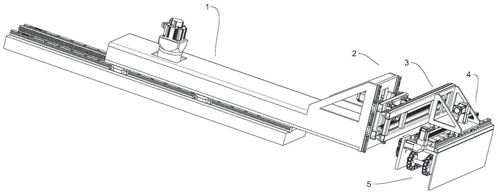
[0038] In this example, if figure 1 , Figure 9 with Figure 10 As shown, a slag removal device on the side of a zinc pot includes an axial translation mechanism 1, a lifting mechanism 2, a first lateral translation mechanism 3 and a slag removal mechanism 5, and the axial translation mechanism 1 is installed in the zinc liquid of the zinc pot In the axial direction of the pool 8, the end of the axial translation mechanism 1 near the center of the zinc liquid pool 8 is equipped with a lifting mechanism 2, and the side of the lifting mechanism 2 near the center of the zinc liquid pool 8 is equipped with a first lateral translation mechanism 3, the first The movement directions of the lateral translation mechanism 3 and the axial translation mechanism 1 are perpendicular to each other, and a slag removal mechanism 5 is installed on the side of the first lateral translation mechanism 3 close to the center of the zinc liquid pool 8 .

[0039]In this embodiment, in order to bette...

Embodiment 2

[0046] On the basis of the first embodiment, this embodiment provides an optional solution for the specific structure of the axial translation mechanism 1:

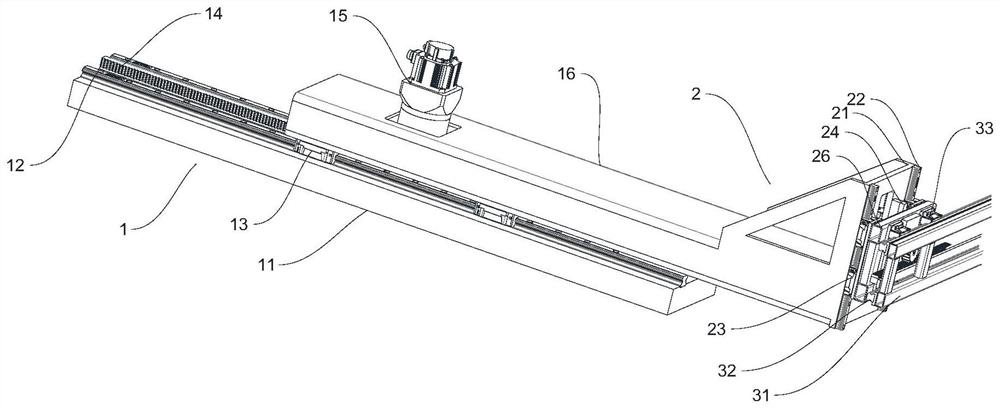
[0047] In this example, if figure 2 , Figure 4 , Figure 6 with Figure 8 As shown, the axial translation mechanism 1 includes a first mounting seat 11, a first slide rail 12, a first sliding member 13, a first driving device 15 and a first movable member 16, and the first mounting seat 11 is installed on the zinc liquid pool 8 One side of the first mounting base 11 is equipped with a first slide rail 12, the first slide rail 12 is installed along the axial direction of the zinc liquid pool 8, and a first slide member 13 is slidably installed on the first slide rail 12. The first movable part 16 is installed on the sliding part 13, the first driving device 15 is installed on the first movable part 16, the first driving device 15 drives the first sliding part 13 to slide along the first slide rail 12, the first movabl...

Embodiment 3

[0051] This embodiment provides an optional solution for the specific structure of the lifting mechanism 2 on the basis of any of the above-mentioned embodiments:

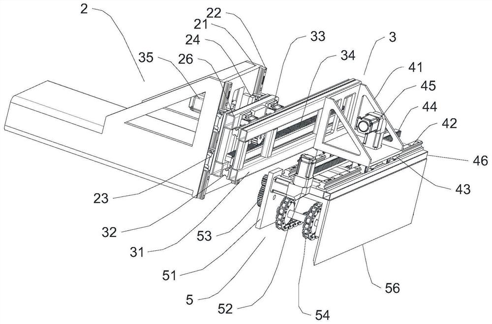
[0052] In this example, if Figure 2-8 As shown, the lifting mechanism 2 includes a second mount 21, a second slide rail 22, a second slider 23, a second rack 24, a second driving device 25 and a second movable part 26; the second mount 21 is vertically Installed on the end of the axial translation mechanism 1 near the zinc liquid pool 8, the second mounting base 21 is vertically installed with a second slide rail 22 near the zinc liquid pool 8, and the second slide rail 22 is slidably installed with a second Slider 23, the second movable member 26 is installed on the second slider 23, the second rack 24 is installed on the second movable member 26, the second rack 24 and the second slide rail 22 are located at the second mounting seat 21 and Between the second movable parts 26 and parallel to each other, the firs...


PUM


Abstract

The invention discloses a slag driving device on the side edge of a zinc pot, and relates to the field of zinc pot automatic slag driving equipment. An oil axial translation mechanism, a lifting mechanism, a first lateral translation mechanism and a slag driving device body are arranged on one side of a zinc liquid pool of the zinc pot, and the axial translation mechanism is used for driving the slag driving device body to move in the axial direction of the zinc liquid pool; the lifting mechanism is used for driving the slag driving device body to ascend and descend, so that the slag driving device body can descend below the liquid level of the zinc liquid pool; and the first lateral translation mechanism is used for driving the slag driving device body to move in the lateral direction of the zinc liquid pool. Through the synergistic effect of the axial translation mechanism, the lifting mechanism and the first lateral translation mechanism, the slag driving device body is used for gathering zinc slag in the zinc liquid pool to a designated position in the movement direction, then through the synergistic effect of a front-end mechanical arm, a V-shaped area chain type slag driving device and a rear-end mechanical arm, manual slag salvaging can be completely replaced, and full-automatic slag salvaging is achieved.

Description

technical field [0001] The invention belongs to the field of automatic slag removal equipment for zinc pots, in particular to a slag removal device for the side edge of a zinc pot. Background technique [0002] In the galvanized sheet and strip production line, the galvanizing process is a crucial link. With the wide application of galvanized sheet and strip, the requirements for the quality of the strip are getting higher and higher. [0003] During the strip galvanizing process, due to the continuous replenishment of zinc material into the zinc pot, the zinc material will also bring a lot of impurities into the zinc pot, and a large amount of scum will be generated on the zinc liquid surface. If it is not cleaned in time, it will be It has a significant impact on the quality of galvanizing on the strip surface. [0004] The galvanizing unit of the strip galvanizing line did not add automatic salvage facilities for zinc dross on the surface of the zinc liquid during the or...

Claims


Application Information

Patent Timeline
Patent Type & Authority Applications(China)
IPC IPC(8): C23C2/06C23C2/40
CPCC23C2/003C23C2/06C23C2/40
Inventor 李强张浩刘瑞
Owner 武汉斯蒂尔派科技有限公司
Why Eureka
Try Eureka