Electric rotating sample holder capable of measuring at any angle
An electric rotation, arbitrary angle technology, applied in the field of optical measurement, can solve the problem of unusable sample holder, poor universality, changing the sample angle, etc., to reduce tooling production and debugging time, accurate measurement results, and reduce the effect of angle error.
- Summary
- Abstract
- Description
- Claims
- Application Information
AI Technical Summary
Problems solved by technology
Method used
Image

Examples
Embodiment 1
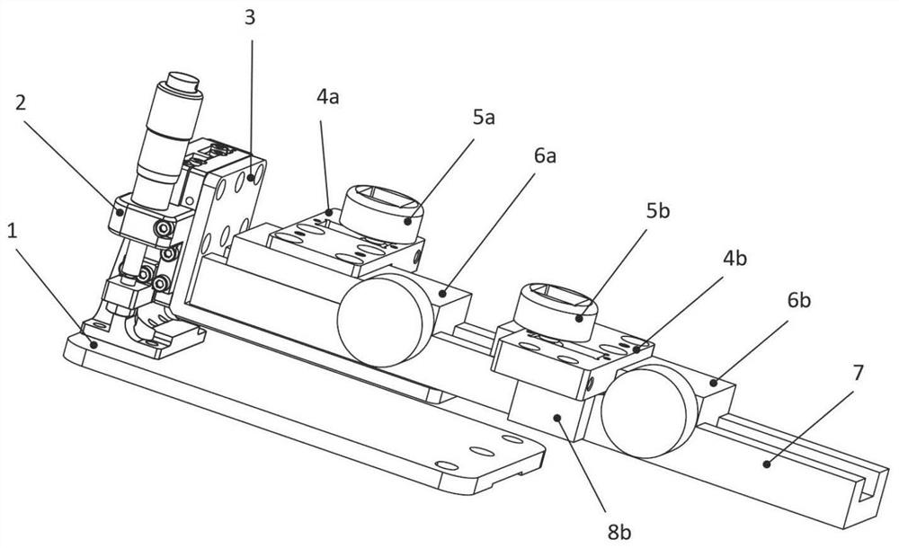
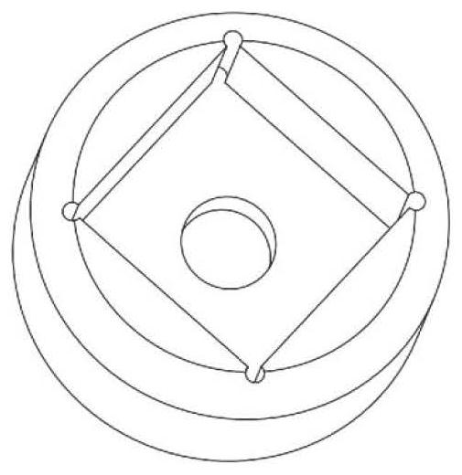
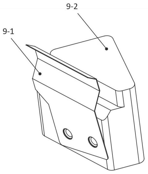
[0034] attached Figure 10 A schematic diagram of the installation of the motorized rotating sample holder that can be measured at any angle is shown, and the device is applicable to a spectrophotometer with a dual optical path system. The device includes connecting bottom plate (1), lifting platform (2), L-shaped support plate (3), guide rail (7), self-locking slider (6), steering gear (8), steering gear fixing plate (4) and samples The platform (5) can perform positioning transmittance detection of the optical thin film device (10). Fix the device in the selected spectrophotometer sample chamber (15) by connecting the base plate (1), as attached Figure 5 Place the crystal sample holder (9) equipped with the optical thin film device (10) to be tested on the sample stage (5) as shown; according to the selected spectrophotometer optical path position, use the lifting platform (2) to adjust the sample stage (5 ) for longitudinal displacement, use the self-locking slider (6) t...
Embodiment 2
[0036] attached Figure 10 A schematic diagram of the installation of the motorized rotating sample holder that can be measured at any angle is shown, and the device is applicable to a spectrophotometer with a dual optical path system. The device includes connecting bottom plate (1), lifting platform (2), L-shaped support plate (3), guide rail (7), self-locking slider (6), steering gear (8), steering gear fixing plate (4) and samples The platform (5) can detect the variable-angle transmittance of the optical thin film device (10). Fix the device in the selected spectrophotometer sample chamber (15) by connecting the base plate (1), as attached Figure 5 As shown, the crystal sample holder (9) equipped with the optical thin film device (10) to be tested is placed on the sample stage (5); according to the selected spectrophotometer optical path position, the sample stage (5a , 5b) carry out longitudinal displacement, and use the self-locking slider (6) to slide on the guide ra...
Embodiment 3
[0038] attached Figure 10 A schematic diagram of the installation of the motorized rotating sample holder that can be measured at any angle is shown, and the device is applicable to a spectrophotometer with a dual optical path system. The device includes connecting bottom plate (1), lifting platform (2), L-shaped support plate (3), guide rail (7), self-locking slider (6), steering gear (8), steering gear fixing plate (4), sample The stage (5) and the polarizer (11) can perform positioning of the optical film device (10) or detection of polarization characteristics with variable angles. Fix the device in the selected spectrophotometer sample chamber (15) by connecting the base plate (1), as attached Figure 5 As shown, the crystal sample holder (9) equipped with the optical thin film device (10) to be measured is placed on the sample stage (5), and the optical thin film device (10) to be measured can be a filter, a dichroic mirror, etc. ;According to the selected optical pat...
PUM
 Abstract
Description
Claims
Application Information
 - R&D Engineer
- R&D Manager
- IP Professional
- Industry Leading Data Capabilities
- Powerful AI technology
- Patent DNA Extraction
Browse by: Latest US Patents, China's latest patents, Technical Efficacy Thesaurus, Application Domain, Technology Topic.
© 2024 PatSnap. All rights reserved.Legal|Privacy policy|Modern Slavery Act Transparency Statement|Sitemap