Method and device for laser welding

a laser welding and laser welding technology, applied in lasers, instruments, manufacturing tools, etc., can solve the problems of limited number of pieces, difficult to obtain good welding, and not particularly wide diffusion of laser welding for said applications, and achieve the effect of reducing production times and high welding quality

Active Publication Date: 2005-07-14
COMAU SPA
View PDF6 Cites 79 Cited by
  • Summary
  • Abstract
  • Description
  • Claims
  • Application Information

AI Technical Summary

Benefits of technology

[0011] The purpose of the present invention is to provide an improved laser-welding method and device, which will be able to exploit the aforesaid underlying idea in a simple and efficient way for the purpose of enabling laser welding of structures such as motor-vehicle bodies or their subassemblies by guaranteeing a high welding quality, but at the same time reducing production times considerably.

Problems solved by technology

The use of laser welding for said applications did, however, not find a particularly wide diffusion immediately after its first proposal, in the early nineties.
This is due principally to the fact that the experiments conducted with the first embodiments of laser-welding devices demonstrated the existence of a wide range of problems connected to said technology.
A first important problem derives from the widespread use, in the automotive field, of sheet steel provided with an outer zinc-coated protective layer.
Said layer gives rise to the generation of zinc vapours during the laser-welding operation, which frequently render it problematical to obtain a good-quality weld.
Another important problem that it is necessary to take into account in the application of laser welding to the assembly of motor-vehicle structures is linked to the need to guarantee a high quality of assembly with reduced production times. A station for assembly of a motor-vehicle body or for its subassembly typically comprises a plurality of locating elements and clamping equipment that ensure correct positioning of the elements of sheet metal constituting the structure during the welding step.
There exists, of course, a minimum limit to the number of pieces of clamping equipment that can be provided for said purpose, below which the geometry of the structure is not adequately guaranteed, with the consequence of an insufficient quality of the assembly operation.
The consequent relative complexity of the structure of the welding station and of its parts obviously renders more difficult the work of the manipulator robots that are used for carrying the welding means (electrical welding guns or yokes in the conventional case, laser heads in the case of laser welding) in the proximity of the various areas of the structure to be welded.
Obviously, the time of stay in the welding station could be reduced by increasing the number of robots, but also in this case there exists a limit to said possibility, which is due both to reasons of costs, and to the fact that, above a certain number of robots, each of the robots becomes an obstacle to the operativeness of one or more robots adjacent to it.
It is necessary to consider, on the other hand, that, at the outset of the application of laser technology to the welding of motor-vehicle structures, the laser generators available were relatively less efficient and less powerful than the ones that are, instead, currently available.
With the first-generation laser generators, it was in any case necessary to guarantee a position of the laser head carried by the robot that was relatively close to the structure to be welded, so that the application of laser technology did not yield particular advantages, from this standpoint, as compared to the traditional electric spot-welding techniques.

Method used


Image

  • Method and device for laser welding
  • Method and device for laser welding
  • Method and device for laser welding

Examples


Embodiment Construction

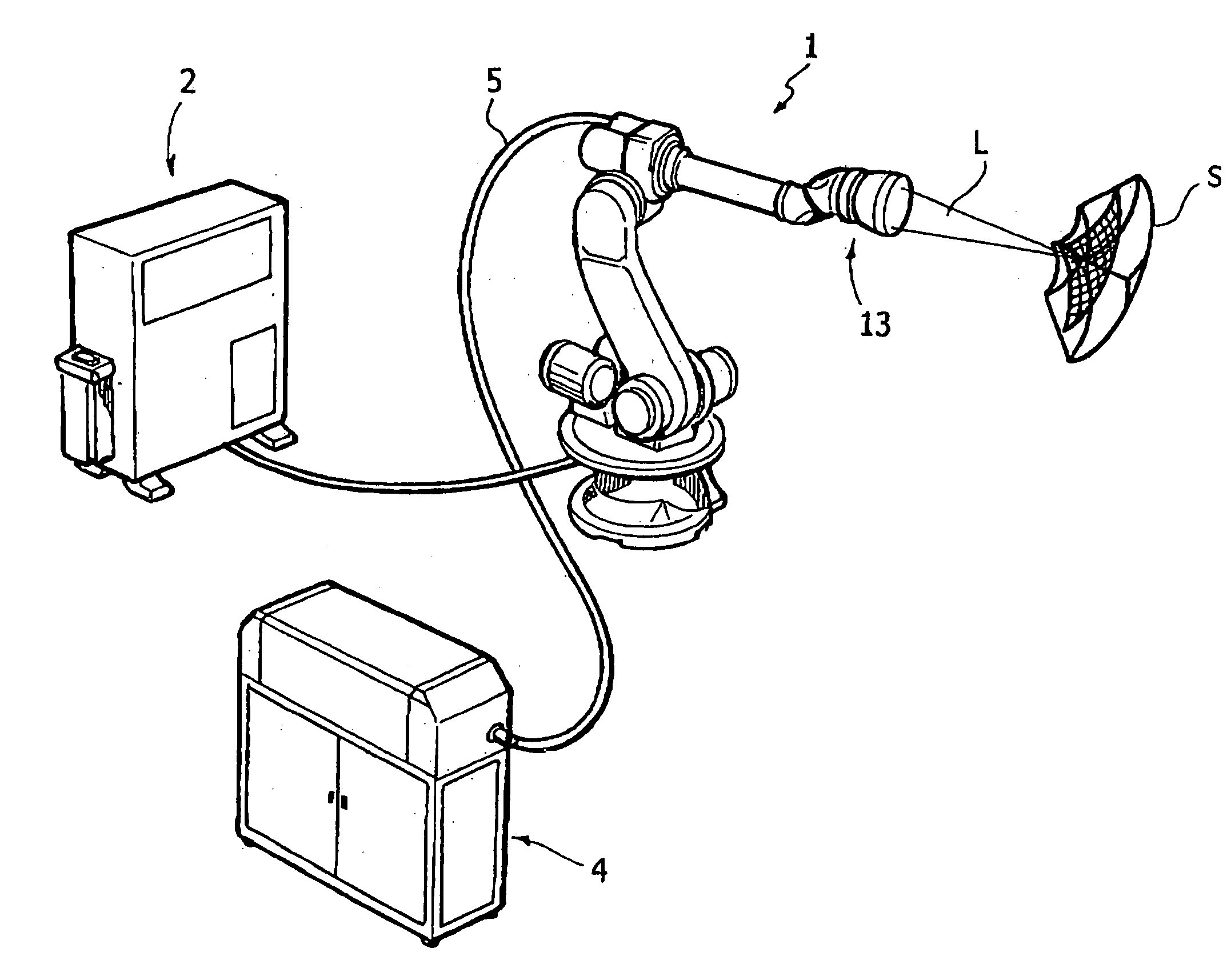
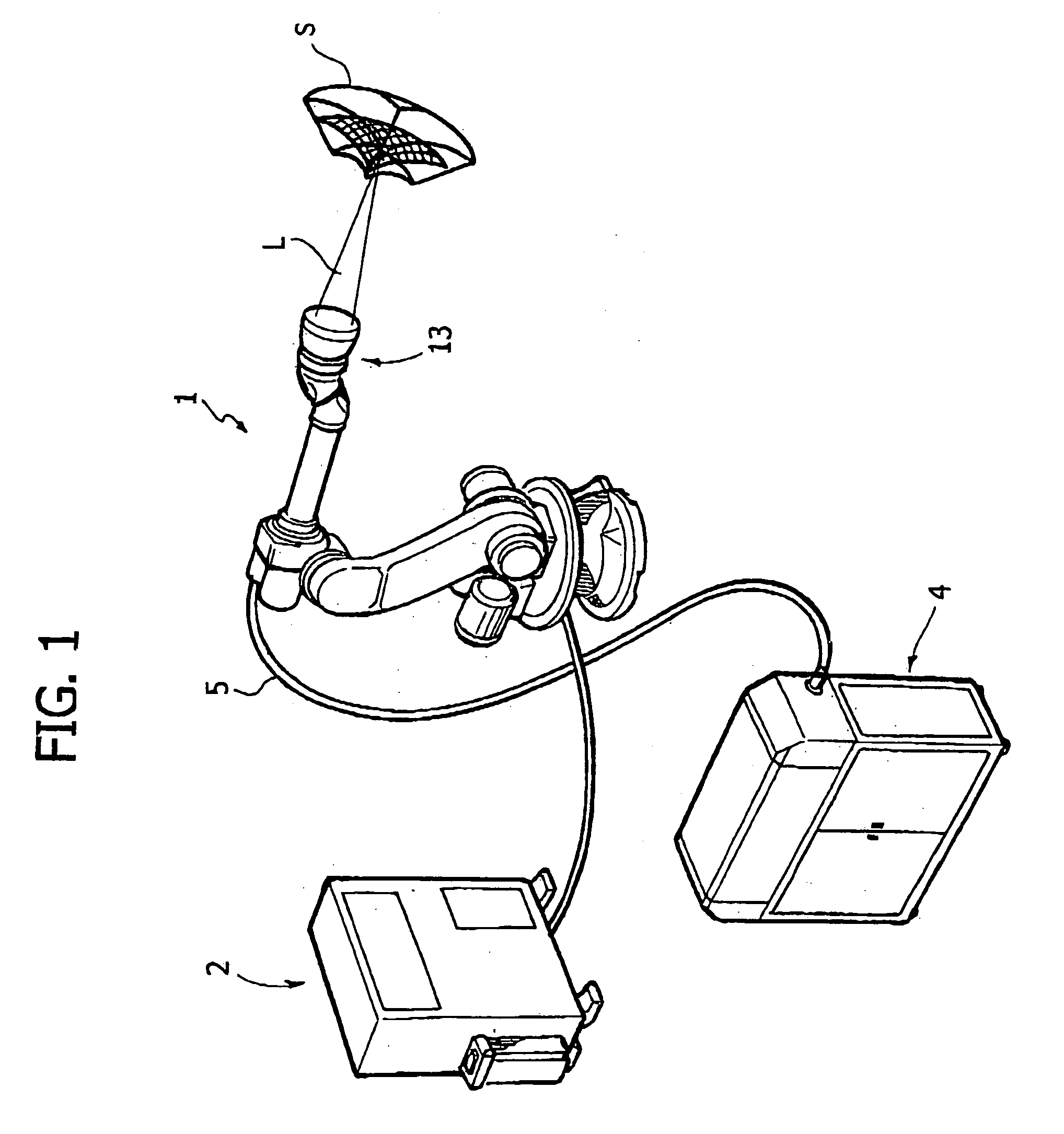
[0022] In FIG. 1, the reference number 1 designates, as a whole, a manipulator robot of any known type. The present applicant has for some time now produced and marketed manipulator robots of an “anthropomorphic” type, which use a set of elements mounted so that they can turn or are articulated with respect to the others according to a respective set of axes (typically six). To each of said axes there is associated an electric control motor. The electric motors are controlled by a control unit 2 connected to the robot. The unit 2 is able to control the electric motors so as to move, in space, the articulated structure of the robot carrying the extreme end of the robot, or “wrist” of the robot, in any point of a space of predetermined shape and dimensions. In the case of the first embodiment of the invention, in the end element of the robot there is integrated a device 3 for focusing and orienting the direction of aiming of a laser beam. The robot 1 is in fact associated to a laser g...


PUM

PropertyMeasurementUnit
areasaaaaaaaaaa
speedaaaaaaaaaa
focusing distanceaaaaaaaaaa

Abstract

A plurality of stretches of laser weld are executed on a structure to be welded by means of a device for focusing and orientation of the laser beam, which is associated to a component element of a manipulator robot. The focusing head is kept in the proximity of, but not closely adjacent to, the different areas to be welded and can consequently follow a simplified path, whilst the device for orientation of the laser beam aims the latter on the different areas of the structure to be welded, so that the speed of travel of the laser beam spot along the longitudinal direction of the weld stretch is independent from the speed of travel of the robot end element.

Description

BACKGROUND OF THE INVENTION [0001] The present invention relates to methods and devices for laser welding, particularly for the welding of structures made of sheet metal constituting assemblies or subassemblies of bodies or frames of motor-vehicles. [0002] The present applicant has proposed for some time now (see, for example, the European patents Nos. EP 0440001 B1 and EP 0440002 B1 regarding the so-called “LASERGATE” system) devices for the laser welding of motor-vehicle structures. The use of laser welding for said applications did, however, not find a particularly wide diffusion immediately after its first proposal, in the early nineties. This is due principally to the fact that the experiments conducted with the first embodiments of laser-welding devices demonstrated the existence of a wide range of problems connected to said technology. [0003] A first important problem derives from the widespread use, in the automotive field, of sheet steel provided with an outer zinc-coated p...

Claims


Application Information

Patent Timeline
Patent Type & Authority Applications(United States)
IPC IPC(8): B23K26/08B23K26/00B23K26/10B23K26/20H01S3/10
CPCB23K26/0807B23K26/246B23K26/0884B23K26/082B23K26/244
Inventor MENIN, ROBERTOBARONCELLI, ARTUROMAULETTI, ENRICO
Owner COMAU SPA
Why Eureka
Try Eureka