Supercharge Your Innovation With Domain-Expert AI Agents!

Array substrate, display panel and display device

An array substrate and display panel technology, applied in nonlinear optics, instruments, optics, etc., can solve problems such as inability to meet users' diverse structural requirements, poor Y-Line half-section, and no signal transmission, etc., to reduce processing costs , Relieve design pressure and material pressure, improve the effect of machining accuracy

Pending Publication Date: 2021-10-29
BOE TECH GRP CO LTD +1
View PDF7 Cites 0 Cited by
  • Summary
  • Abstract
  • Description
  • Claims
  • Application Information

AI Technical Summary

Problems solved by technology

[0002] Existing full-screen mobile phones usually design a transparent area where the camera is placed in the upper middle of the screen. At present, the most popular area in this area is the round hole (Punch, commonly known as the blind hole), or the Notch (including the U-shaped groove commonly known as Qi Liuhai, the beauty sharp V-shaped grooves, drop-shaped grooves), with the diversification and diversification of mobile phones and other electronic products, users have more and more demands on product structures. higher cost
[0003] In addition, in the traditional product design process, the blind hole or Notch generally adopts the form of GOA (Gate Drive On Array, the gate drive circuit installed on the array substrate) unilateral drive, that is, the left and right GOAs respectively drive the gates of different rows. (Gate) pixels, when there is a problem with the first-level GOA or a row of gates (for example, the above-mentioned Notch is formed during special-shaped cutting), the pixels in this row will have no signal transmission, and the Y-Line half-section line will be defective.

Method used


Image

  • Array substrate, display panel and display device
  • Array substrate, display panel and display device
  • Array substrate, display panel and display device

Examples


Embodiment Construction

[0031] Various aspects and features of the present disclosure are described herein with reference to the accompanying drawings.

[0032] It should be understood that various modifications may be made to the embodiments applied for herein. Accordingly, the above description should not be viewed as limiting, but only as exemplifications of embodiments. Those skilled in the art will envision other modifications within the scope and spirit of the disclosure.

[0033] The accompanying drawings, which are incorporated in and constitute a part of this specification, illustrate embodiments of the disclosure and, together with the general description of the disclosure given above and the detailed description of the embodiments given below, serve to explain the embodiments of the disclosure. principle.

[0034] These and other characteristics of the present disclosure will become apparent from the following description of preferred forms of embodiment given as non-limiting examples wi...


PUM


Abstract

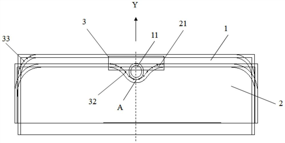
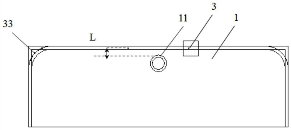
The invention relates to an array substrate, a display panel and a display device. The array substrate comprises a first substrate which comprises a trepanning area; and a second substrate, wherein the second substrate and the first substrate are oppositely arranged in an overlapped mode, the edge of at least one side of the second substrate is provided with an opening area, the opening area surrounds the trepanning area, and at least part of the edge of the trepanning area is tangent to at least part of the edge of the opening area. The array substrate is configured to be the first substrate and the second substrate which are overlapped up and down, the trepanning area is formed in the first substrate, and the opening area which can surround the trepanning area and is tangent to at least part of the edge of the opening area is formed in the second substrate, so that only one set of process design is needed, different product structure requirements of users can be met, the alignment problem during different special-shaped cutting is solved, the product machining precision is improved, the design pressure and the material pressure during product design and machining are greatly relieved, and the machining cost is effectively reduced.

Description

technical field [0001] The present disclosure relates to the field of display technology, in particular to an array substrate, a display panel and a display device. Background technique [0002] Existing full-screen mobile phones usually design a transparent area where the camera is placed in the upper middle of the screen. At present, the most popular area in this area is the round hole (Punch, commonly known as the blind hole), or the Notch (including the U-shaped groove commonly known as Qi Liuhai, the beauty sharp V-shaped grooves, drop-shaped grooves), with the diversification and diversification of mobile phones and other electronic products, users have more and more demands on product structures. higher cost. [0003] In addition, in the traditional product design process, the blind hole or Notch generally adopts the form of GOA (Gate Drive On Array, the gate drive circuit installed on the array substrate) unilateral drive, that is, the left and right GOAs respective...

Claims


Application Information

Patent Timeline
Patent Type & Authority Applications(China)
IPC IPC(8): G02F1/1362
CPCG02F1/1362G02F1/136204
Inventor 刘弘徐敬义黄波刘鹏张永强李志明梁朝霍培荣肖振宏丁爱宇李波王国栋韩帅
Owner BOE TECH GRP CO LTD
Features
  • R&D
  • Intellectual Property
  • Life Sciences
  • Materials
  • Tech Scout
  • Unparalleled Data Quality
  • Higher Quality Content
  • 60% Fewer Hallucinations
Learn More