Radar touch point fusion filtering method and system, electronic equipment and storage medium

A filtering method and touch point technology, which is applied in the field of radar scanning, can solve problems such as false triggering of touch points in the scanning area, interference with normal use, and small scanning range

Pending Publication Date: 2021-10-29
海南雷影信息技术有限公司
View PDF0 Cites 0 Cited by
  • Summary
  • Abstract
  • Description
  • Claims
  • Application Information

AI Technical Summary

Problems solved by technology

[0003] In practical applications, when the scanning device installed by the radar scans, the scanned area is fan-shaped, which results in more points scanned by objects closer to the device, and smaller range scanned by objects farther away from the device.
And in special cases, when the scanned wall is uneven, or there are disturbances on the scanned ground, it will cause the scanning area to continuously trigger the touch point by mistake, interfering with normal use

Method used


Image

  • Radar touch point fusion filtering method and system, electronic equipment and storage medium
  • Radar touch point fusion filtering method and system, electronic equipment and storage medium
  • Radar touch point fusion filtering method and system, electronic equipment and storage medium

Examples


Embodiment

[0037] After long-term research and practice, the inventor of the present application found that in the prior art, when the scanning device installed with radar scans, the scanning area is fan-shaped, which causes the closer the object to the device to scan, the more points it scans. More, the farther the object is, the smaller the scanning range will be. And in special cases, when the scanned wall is uneven, or there are disturbing objects on the scanned ground, it will cause the scanning area to continuously trigger the touch point by mistake, interfering with normal use.

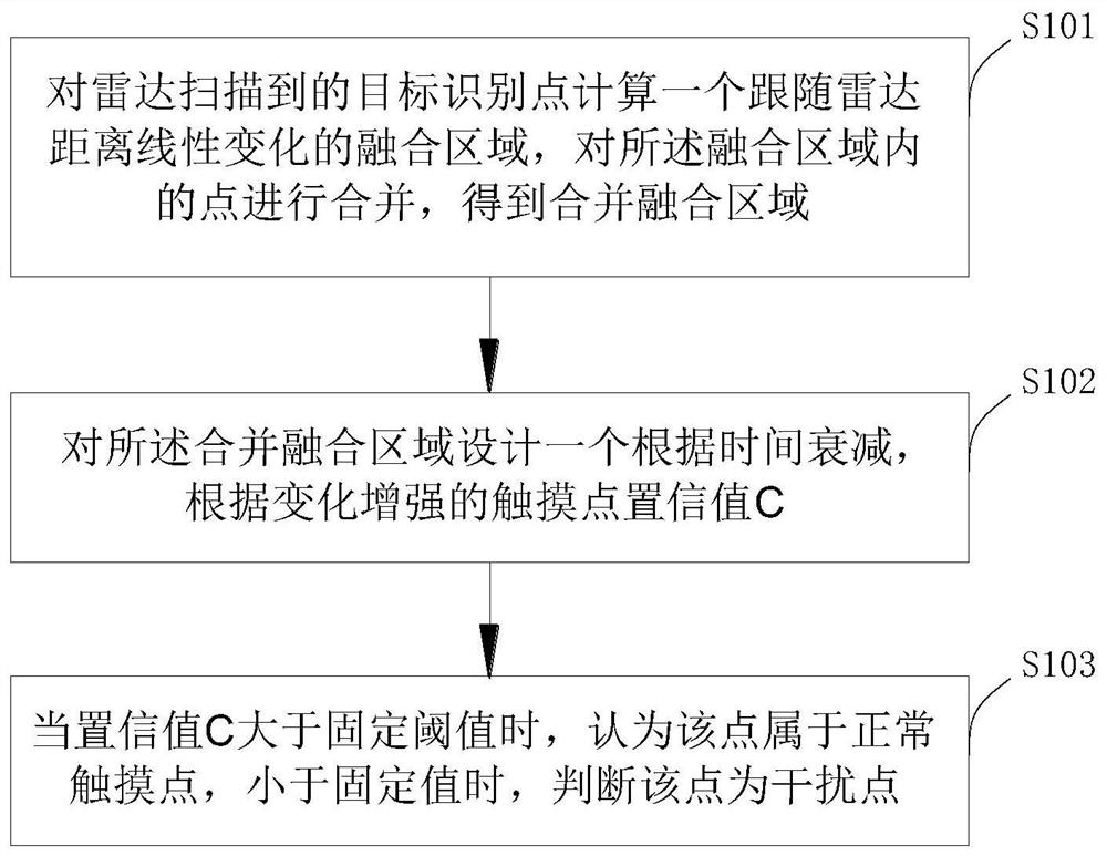
[0038] For this reason, please refer to figure 1 In a first aspect, an embodiment of the present invention provides a radar touch point fusion filtering method, including:

[0039] S101: Calculate a fusion area following the linear change of the radar distance for the target recognition points scanned by the radar, and merge the points in the fusion area to obtain a fusion area;

[0040] S102: Design a ...


PUM


Abstract

The invention discloses a radar touch point fusion filtering method and system, electronic equipment and a storage medium, and relates to the technical field of radar scanning, and the method comprises the steps: calculating a fusion region which linearly changes along with the radar distance for target recognition points scanned by a radar, and merging the points in the fusion region to obtain a merged fusion region; designing a touch point confidence value C which is attenuated according to time and enhanced according to change for the merging and fusing area; and when the confidence value C is greater than a fixed threshold value, determining that the target identification point belongs to a normal touch point, and when the confidence value C is less than a fixed value, determining that the target identification point is an interference point. The system comprises a merging and fusing module, a confidence value module and a judgment module. Herein, the interference generated under normal conditions can be quickly eliminated, a user is prevented from being continuously interfered by some non-real interferents, and the working efficiency is improved.

Description

technical field [0001] The invention relates to the technical field of radar scanning, in particular to a radar touch point fusion filtering method, system, electronic equipment and storage medium. Background technique [0002] Radar is a transliteration of English Radar, derived from the abbreviation of radio detection and ranging, meaning "radio detection and ranging", that is, to use radio methods to find targets and determine their spatial positions. Therefore, radar is also called "radiolocation". Radar is an electronic device that uses electromagnetic waves to detect objects. The radar emits electromagnetic waves to irradiate the target and receives its echo, thereby obtaining information such as the distance from the target to the electromagnetic wave emission point, the distance change rate (radial velocity), azimuth, and height. [0003] In practical applications, when the scanning device installed with radar scans, the scanned area is fan-shaped, which results in...

Claims


Application Information

Patent Timeline
IPC IPC(8): G06F3/041G06F3/043
CPCG06F3/04166G06F3/043
Inventor 方鸿亮白金涛陈哲祥
Owner 海南雷影信息技术有限公司
Why Eureka
Try Eureka