
Analysis portion, time-of-flight imaging device and method

A time-of-flight, imaging device technology, applied in measurement devices, image analysis, image enhancement and other directions, can solve problems such as time-consuming

Pending Publication Date: 2021-10-29
SONY SEMICON SOLUTIONS CORP
View PDF0 Cites 0 Cited by
  • Summary
  • Abstract
  • Description
  • Claims
  • Application Information

AI Technical Summary

Problems solved by technology

[0003] To measure distance, time-of-flight devices are known to traverse thousands or millions of measurement cycles, which can result in a time-consuming process

Method used


Image

  • Analysis portion, time-of-flight imaging device and method
  • Analysis portion, time-of-flight imaging device and method
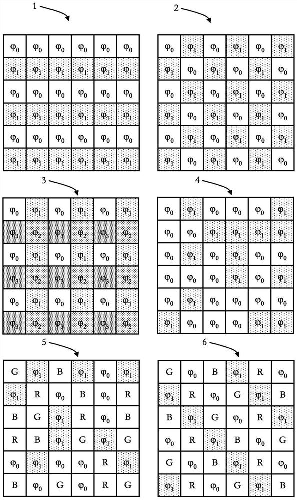
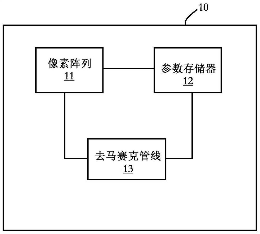
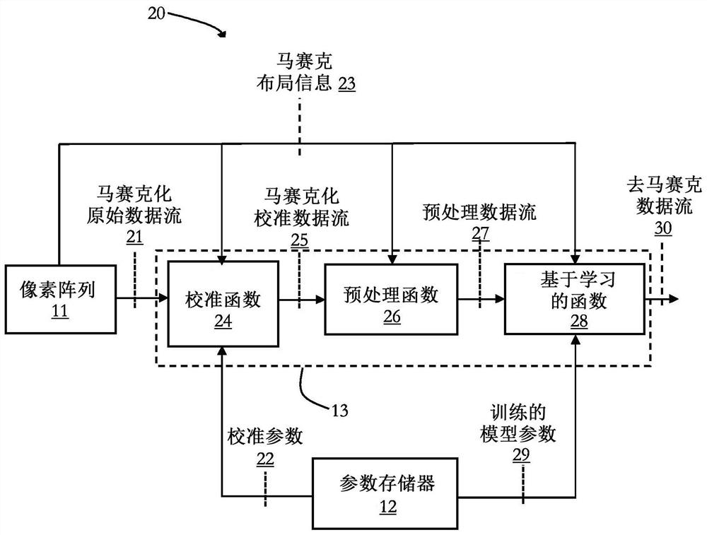
  • Analysis portion, time-of-flight imaging device and method

Examples


Embodiment Construction

[0021] in giving reference figure 1 Before the detailed description of the embodiments, a general explanation is provided.

[0022] As already explained at the outset, it is generally desirable to have a small number (eg one) of imaging cycles. Therefore, it has been recognized that complex algorithms must be found in order to be able to demosaic raw imaging data acquired with a small number of imaging cycles.

[0023] Accordingly, some embodiments relate to an analysis section for a time-of-flight imaging section, wherein the time-of-flight imaging section comprises at least one imaging element of a first type and at least one imaging element of a second type, wherein at least one imaging element of the first type The elements and the at least one imaging element of the second type are arranged in a predetermined pattern, wherein the analyzing part is configured to construct a first image of the at least one imaging element of the first type based on second imaging element d...


PUM


Abstract

The present disclosure pertains to an analysis portion for a time-of-flight imaging portion, wherein the time-of-flight imaging portion includes at least one imaging element of a first type and at least one imaging element of a second type, wherein the at least one imaging element of the first type and the at least one imaging element of the second type are arranged in a predetermined pattern, configured to: construct first imaging data of the at least one imaging element of the first type based on second imaging element data of the at least one imaging element of the second type, wherein the first imaging data are constructed based on a machine learning algorithm.

Description

technical field [0001] The present disclosure generally relates to an analysis section for a time-of-flight imaging section, a time-of-flight imaging device and a method for controlling a time-of-flight imaging section. Background technique [0002] In general, time-of-flight (ToF) devices are known for eg imaging or creating a depth map of a scene such as an object, a person, or the like. A distinction can be made between direct ToF (dToF) and indirect ToF (iToF) to measure distance by measuring the transit time (dToF) of emitted and reflected light or by measuring one or more phase shifts (iToF) of emitted and reflected light. [0003] To measure distance, known time-of-flight devices need to go through thousands or millions of measurement cycles, which can result in a time-consuming process. Furthermore, in order to reduce the number of measurement cycles while maintaining a complex imaging chip that is also able to acquire information other than depth / distance informati...

Claims


Application Information

Patent Timeline
Patent Type & Authority Applications(China)
IPC IPC(8): G01S7/4912G01S17/894G01S7/481
CPCG01S17/894G01S7/4816G01S7/4912G01S17/36G01S7/497G01S17/86G06T7/521G06T2207/10028G06T2207/20081
Inventor 瓦莱里奥·坎巴雷里卢卡·卡特赖内利拉基·莫汉
Owner SONY SEMICON SOLUTIONS CORP
Learn More