Circular sheet stacking and polishing device and stacking and polishing method thereof

A wafer and driving device technology, which is applied in the direction of grinding driving device, grinding machine, grinding feed movement, etc., can solve the problems of labor cost and burrs on the edge of the wafer, and achieve the effect of improving work efficiency

Active Publication Date: 2021-11-02
福安市中虹机电技术开发有限公司
View PDF10 Cites 6 Cited by
  • Summary
  • Abstract
  • Description
  • Claims
  • Application Information

AI Technical Summary

Benefits of technology

The technical effect described this technology simplifies the process of cleanlinessally shaping wafers during manufacturing processes without requiring any extra steps or equipment like manual tools such as buffers. This results in improved productivity due to faster rotation times between different layers within each section of the final structure formed from multiple sheets.

Problems solved by technology

This patented describes how it was necessary in order to achieve efficient manufacturing by automatically collecting and processing large amounts of sheet metal during its formation on roll form machines before further use or sale. However, manual collection methods were time-consuming and resulted in scrapings at certain points along their edges due to sharp corner features formed when they hit other parts inside them. Therefore there has been research conducted towards developing better ways to efficiently store and sort these sheets without damaging themselves.

Method used


Image

  • Circular sheet stacking and polishing device and stacking and polishing method thereof
  • Circular sheet stacking and polishing device and stacking and polishing method thereof

Examples


Embodiment 1

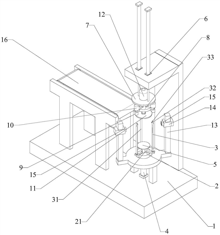
[0071] A wafer stacking and grinding device, comprising:

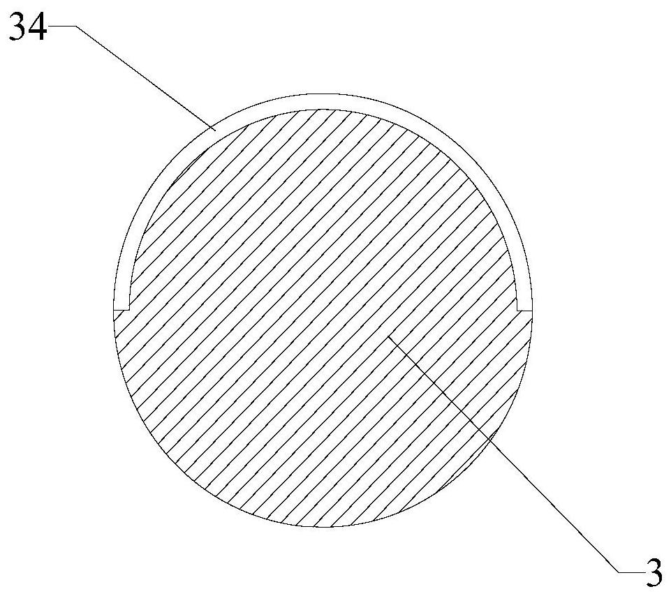
[0072] The base 1; the first three-jaw chuck 2, the first three-jaw chuck 2 is connected to the upper part of the base 1, and the middle part of the first three-jaw chuck 2 is provided with a first through hole 21 in a vertical direction; Positioning posts 3, the three limiting posts 3 are respectively vertically and rotatably connected to the upper part of the jaws of the three-jaw chuck, one side of the limiting posts 3 is provided with a frosted layer 31; the limiting posts 3 The other side is a smooth surface; the first cylinder 4, the cylinder body of the first cylinder 4 is fixed on the base 1, and the piston rod of the first cylinder 4 passes through the first through hole 21 vertically; A turntable 5, the first turntable 5 is connected to the top of the piston rod of the first cylinder 4; the second cylinder 6, the second cylinder 6 is arranged vertically downwards above the turntable; connecting plate 7, the c...

Embodiment 2

[0076] The wafer stacking and grinding method of the above-mentioned wafer stacking and grinding device includes the following steps:

[0077] Step 1: Adjust the first three-jaw chuck 2 and the second three-jaw chuck 8, so that the diameter of the cylinder on the inner side of the three limit posts 3 is equal to the diameter of the disc, and make each limit sleeve 9 and each limit The upper ends of the columns 3 correspond one by one, and at this time, the side of each limiting column 3 with the frosted layer 31 faces outward;

[0078] Step 2: PLC controls the first cylinder 4 to drive the first turntable 5 up to a preset height, and the wafers drop to the first turntable 5 continuously, and are stacked on the upper part of the first turntable 5 under the limit action of the limit column 3 , when the height of the wafer stack is higher than the height of the photoelectric sensor 15, the receiving end of the photoelectric sensor 15 does not receive the light signal, and the PLC...


PUM


Abstract

The invention relates to the technical field of motor machining, in particular to a circular sheet stacking and polishing device and a stacking and polishing method thereof. According to the method, a circular sheet obtained through stamping can automatically fall to the upper portion of a first rotary disc after being conveyed by a conveying belt, after stacking is completed, an upper connecting plate moves downwards, then an upper limiting sleeve matches the upper portion of a limiting column in a limiting mode, the limiting sleeve drives the limiting column to rotate by 90 degrees, a frosted layer of the limiting column faces inwards, a second rotary disc and the first rotary disc clamp the stacked circular sheet, all stacked circular sheets can be driven to rotate together by driving the second rotary disc to rotate, and sliding friction is generated between the edge of the circular sheet and the frosted layer of the limiting column, so that the purpose of polishing burrs on the edge of the circular sheet is achieved, the circular sheet does not need to be manually and additionally treated, additional procedures for polishing the burrs on the edge of the circular sheet are not needed, and the working efficiency is greatly improved.

Description


Claims


Application Information

Patent Timeline
Owner 福安市中虹机电技术开发有限公司
Why Eureka
Try Eureka