
Intelligent ventilation device for building construction

A ventilation device, an intelligent technology, applied in the ventilation system, space heating and ventilation, space heating and ventilation details, etc., can solve the problems affecting the normal activities of residents, reducing the air supply volume, increasing the fan load, etc., to achieve convenient cleaning operations. , Extend the service life and ensure the effect of smooth air supply

Inactive Publication Date: 2021-11-02
安徽恒晟揽智科技有限公司
View PDF0 Cites 1 Cited by
  • Summary
  • Abstract
  • Description
  • Claims
  • Application Information

AI Technical Summary

Problems solved by technology

After the building is completed, the ventilation device is indispensable. It is mainly installed in the basement, and the ventilation device is used to supply air to the basement and other unventilated places, so as to prevent people from breathing poorly due to lack of oxygen in the activity room in such a place, which is harmful to the personnel. Life and property will cause irreparable losses, but in the actual building construction process, the developer only needs to simply decorate the basement to ensure basic ventilation and fire protection. A large amount of dust will be introduced during the air supply. In order to reduce the impact on the respiratory system of personnel, the ventilation device often uses a filter device to purify and filter the air. However, the filter screen is in a high-concentration wind-dust environment for a long time, and it is very easy to block. Once the filter launch tube is blocked, it will not only increase the load of the fan, but also reduce the air supply volume, seriously affecting the normal activities of residents in the basement.

Method used


Image

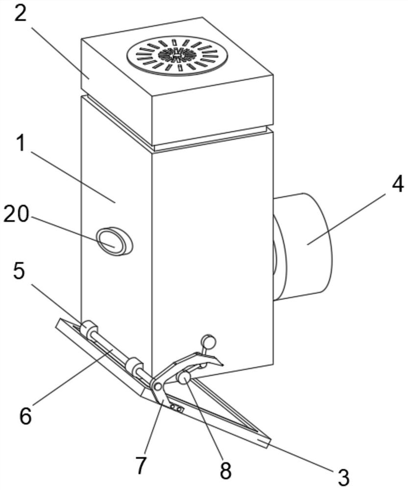
  • Intelligent ventilation device for building construction
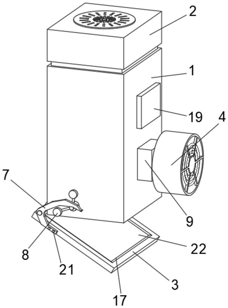
  • Intelligent ventilation device for building construction
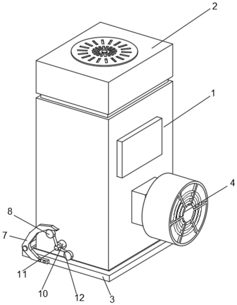
  • Intelligent ventilation device for building construction

Examples


Embodiment Construction

[0026] The following will clearly and completely describe the technical solutions in the embodiments of the present invention with reference to the accompanying drawings in the embodiments of the present invention. Obviously, the described embodiments are only some, not all, embodiments of the present invention.

[0027] Examples of embodiments are shown in the drawings, wherein like or similar reference numerals denote like or similar elements or elements having same or similar functions throughout. The embodiments described below by referring to the figures are exemplary and are intended to explain the invention and should not be construed as limitations of the invention.

[0028] In describing the invention, it is to be understood that the terms "center", "longitudinal", "transverse", "length", "width", "thickness", "upper", "lower", "front", " Back", "Left", "Right", "Vertical", "Horizontal", "Top", "Bottom", "Inner", "Outer", "Clockwise", "Counterclockwise", "Axial", The...


PUM


Abstract

The invention discloses an intelligent ventilation device for building construction. The intelligent ventilation device comprises a ventilation shell, an induced draft fan and a partition plate, the bottom and the top of the ventilation shell are each of an opening structure, the induced draft fan is installed at the opening of the top of the ventilation shell in a sealed mode, and the partition plate is hinged to the opening of the bottom of the ventilation shell; a filter plate for filtering air is arranged in the ventilation shell; and the intelligent ventilation device further comprises a dust removal assembly arranged on the ventilation shell and used for conducting reverse blowing on the filter plate. The ventilation device is provided with a reverse blowing fan used for carrying out dust removal operation on the filter plate in the ventilation device, air flow of the reverse blowing fan ejects a second check valve open, enters the ventilation shell and blows towards the filter plate, a first check valve is closed, the air flow reversely blows dust on the filter plate to fall off, and the dust is discharged from an air outlet along with the air flow, so that ash removal treatment and maintenance of the filter plate are realized.

Description

technical field [0001] The invention relates to the technical field of intelligent ventilation, in particular to an intelligent ventilation device for building construction. Background technique [0002] With the continuous progress of the society, there are more and more urban residents, resulting in an exponential increase in the number of urban buildings. Now the property market is becoming more and more diversified. According to different age groups, the types of buildings are also different. But people are eternal and constant to the overall ventilation property requirement of building whole. After the building is completed, the ventilation device is indispensable. It is mainly installed in the basement, and the ventilation device is used to supply air to the basement and other unventilated places, so as to prevent people from breathing poorly due to lack of oxygen in the activity room in such a place, which is harmful to the personnel. Life and property will cause irr...

Claims


Application Information

Patent Timeline
IPC IPC(8): F24F7/003F24F8/108F24F8/90F24F11/89F24F13/08F24F13/28F24F110/76
CPCF24F7/003F24F8/108F24F8/90F24F13/08F24F11/89F24F13/28F24F2110/76
Inventor 施宏达吴丹丹
Owner 安徽恒晟揽智科技有限公司
Learn More