
Roadway impact resistance calculation method considering support-pressure relief-surrounding rock coupling effect

A calculation method and impact resistance technology, applied in the direction of using a single impact force to test the strength of materials, measuring devices, instruments, etc., can solve the problems of not considering the effect of pressure relief holes, not in line with engineering practice, and unable to fully reflect the impact resistance of roadways. , to achieve the effect of high safety factor

Pending Publication Date: 2021-11-02
SHANDONG UNIV OF SCI & TECH
View PDF1 Cites 4 Cited by
  • Summary
  • Abstract
  • Description
  • Claims
  • Application Information

AI Technical Summary

Problems solved by technology

The roadway resists the impact ground pressure in the form of a whole, not the result of the independent action of the roof or the side; The capacity calculation method cannot fully reflect the actual impact resistance of the roadway
[0006] (2) The coupling effect between the support structure and the surrounding rock is not considered
The support structure and the surrounding rock form a unified anchor bearing body, which will produce displacement and deformation after being subjected to the impact load together. actual
[0007] (3) The pressure relief effect is not considered
In rock burst roadways, large-diameter borehole pressure relief has become a customary measure, which has an important influence on the calculation of the impact resistance of anchorage bearing structures and is a factor that must be considered. None of the existing calculation methods for impact resistance Consider the role of pressure relief holes

Method used


Image

  • Roadway impact resistance calculation method considering support-pressure relief-surrounding rock coupling effect
  • Roadway impact resistance calculation method considering support-pressure relief-surrounding rock coupling effect
  • Roadway impact resistance calculation method considering support-pressure relief-surrounding rock coupling effect

Examples


Embodiment 1

[0059] Taking a certain rockburst mine as a specific example below, this patent is further described:

[0060] Step 1: Investigate the relevant engineering support parameters of the specific roadway at the site

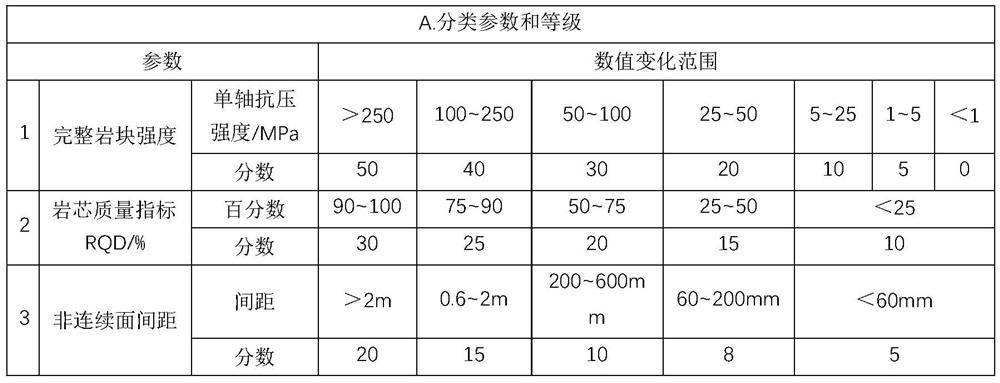
[0061] (1) Roadway engineering geological parameters. According to the survey, the complete rock block strengths of the roadway roof and the two sides are 132MPa and 35MPa respectively; the core quality indicators RQD are 64 / % and 34 / % respectively; the distance between discontinuous surfaces is 232mm and 189mm respectively;

[0062] (2) Roadway specific support parameters. ① Roadway size parameters: roadway width A is 4.8m, roadway height B is 5.2m; ② roadway support parameters: length of roof anchor l g1 2.4m, the diameter of the anchor rod is 22mm, the row spacing is 850mm, the spacing is 800mm, the length of the roof anchor cable is l s1 is 6.2m, the diameter of the anchor cable is 22mm, the row spacing is 1200mm, and the spacing is 1600mm; the length of the tw...


PUM

PropertyMeasurementUnit
elastic modulusaaaaaaaaaa
yield strengthaaaaaaaaaa
lengthaaaaaaaaaa

Abstract

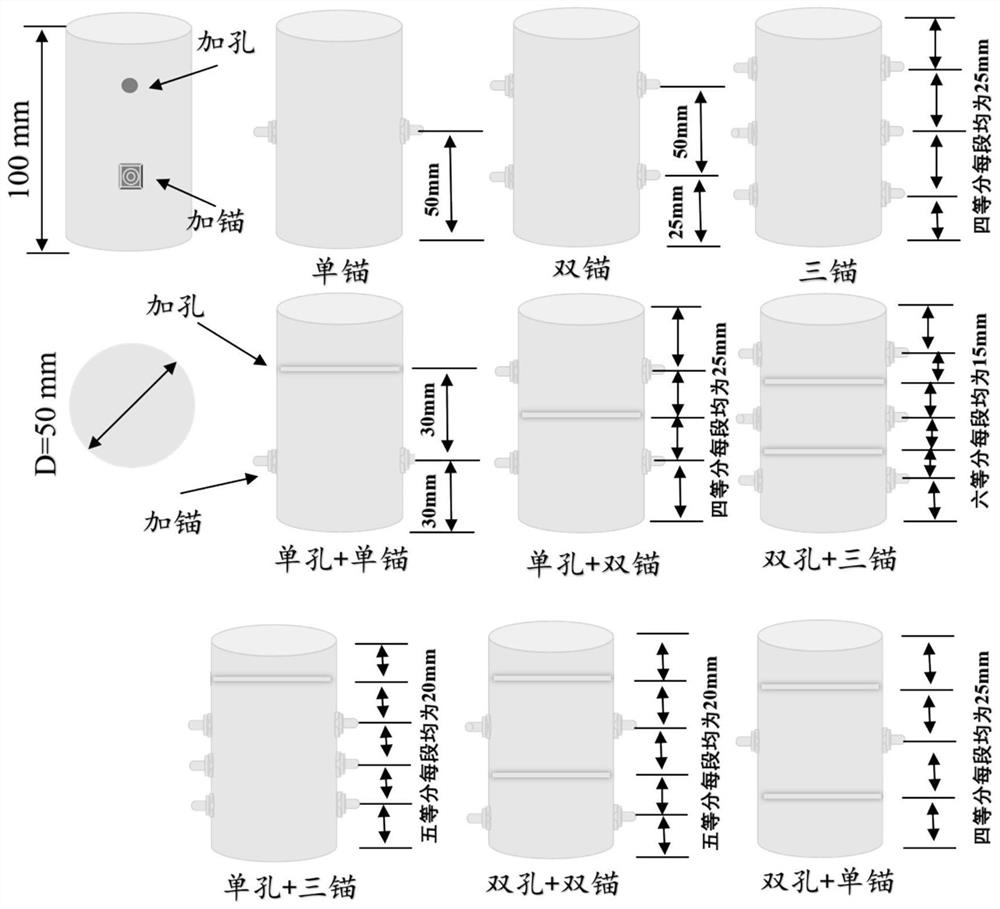
The roadway impact resistance calculation method considering the support-pressure relief-surrounding rock coupling effect comprises steps of the corresponding test piece strength being determined according to the roadway surrounding rock strength grade, and the top plate support grade and the test piece type being determined by using the support parameters of the top plate; comprehensively considering support parameters and pressure relief parameters of two sides of the roadway, and determining test piece types of the two sides; determining an anchoring position according to the type of a top plate test piece, determining the anchoring position and a hole adding position according to the types of two side test pieces, and manufacturing a test piece meeting the requirements; performing a dynamic impact test and test piece energy calculation on the test piece, performing indoor test piece manufacturing and testing according to field engineering conditions, and calculating anchoring surrounding rock bearing energy of unit volume of two sides and a roof according to a stress-strain curve obtained by the test; finally, a calculation result being converted into field engineering for energy calculation of the roadway anchoring bearing structure.

Description

technical field [0001] The invention relates to a roadway anti-shock calculation method considering the coupling effect of support-pressure relief-surrounding rock. Background technique [0002] In recent years, with the increasing depth and intensity of coal mine mining in my country, the distribution range and quantity of rock burst mines have become larger and larger, and the occurrence frequency and damage degree of rock burst have become more intense, often causing equipment damage and casualties. Pressure disasters have become the main disasters restricting the safe, high-yield and efficient mining of coal mines. According to statistics, 90% of rock burst disasters occur in roadways, and reasonable anti-scour measures for roadways can effectively reduce or avoid damage caused by rock bursts. Support and pressure relief for large diameter boreholes. Under the conditions of strengthened support and large-diameter pressure relief, the impact resistance value is a compreh...

Claims


Application Information

Patent Timeline
Patent Type & Authority Applications(China)
IPC IPC(8): G01N3/30G01N3/02
CPCG01N3/30G01N3/02G01N2203/001G01N2203/0075
Inventor 张广超李友陶广哲张书磊左昊曲治陈淼蒋邦友
Owner SHANDONG UNIV OF SCI & TECH
Learn More