Method and device for judging leakage protection starting and delay action of power grid

A technology of leakage protection and time-delayed action, which is applied in the direction of automatic disconnection emergency protection device, emergency protection circuit device, circuit device, etc., can solve the problems that the leakage protection technology has not been effectively solved, the protection dead zone is large, and the setting is complicated. , to achieve the effect of reducing the protection dead zone, reducing protection misoperation and high protection sensitivity

Pending Publication Date: 2021-11-02
GUANGDONG POWER GRID CO LTD +1
View PDF0 Cites 1 Cited by
  • Summary
  • Abstract
  • Description
  • Claims
  • Application Information

AI Technical Summary

Problems solved by technology

However, the above method still has problems such as complicated setting, large protection dead zone, and easy misoperation, and has not been applied on a large scale.
Therefore, the problems existing in leakage protection technology have not been effectively resolved, and it is necessary to study new protection methods

Method used


Image

  • Method and device for judging leakage protection starting and delay action of power grid
  • Method and device for judging leakage protection starting and delay action of power grid
  • Method and device for judging leakage protection starting and delay action of power grid

Examples


Embodiment 1

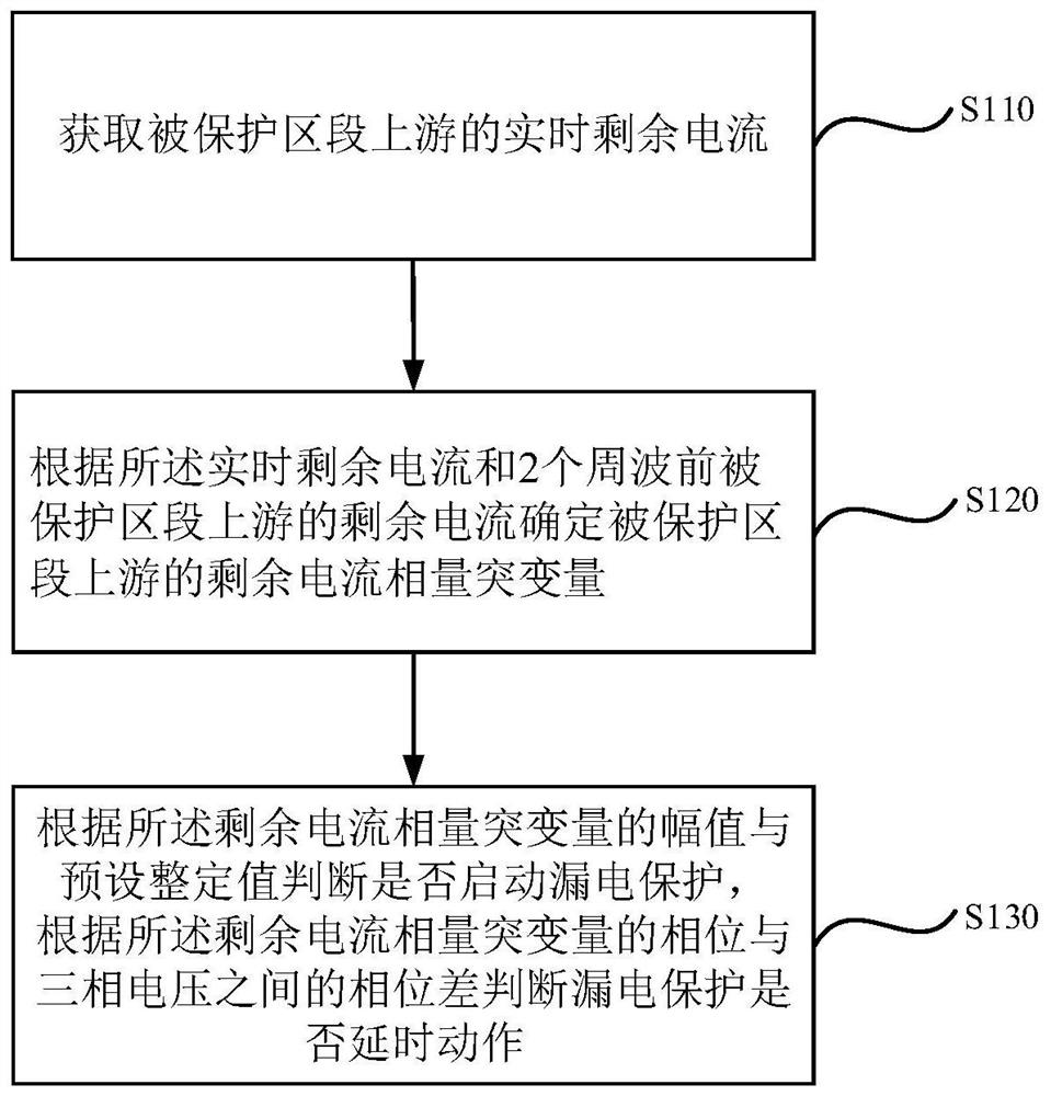
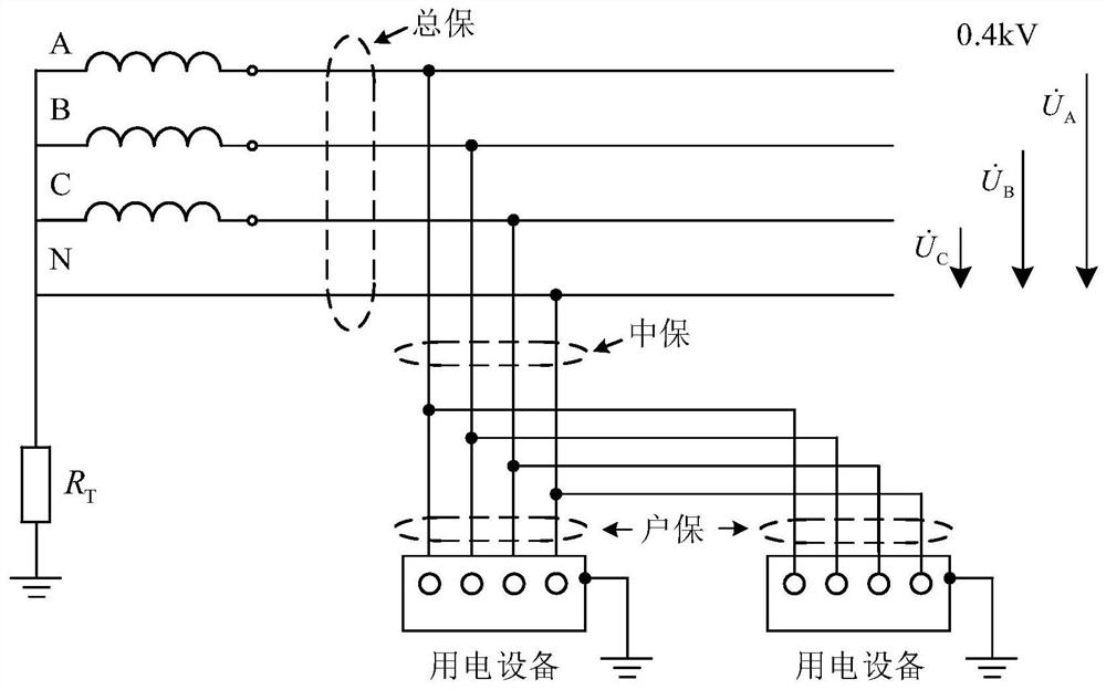
[0050] figure 1 It is a flow chart of the power grid leakage protection startup and delay action judging method in Embodiment 1 of the present invention, figure 2 It is a schematic diagram of the installation position of the new residual current operating protection device provided by Embodiment 1 of the present invention. This embodiment is applicable to the situation of leakage fault in the power grid, and the method can be executed by the leakage protection startup judgment device. refer to figure 1 , the control method includes the following steps:

[0051] S110. Obtain the real-time residual current upstream of the protected section.

[0052]Among them, the residual current is the leakage current, and the instantaneous current flowing through the main circuit of the residual current action protection device is the effective value of the current. The residual current refers to the current in which the vector sum of the currents of each phase (including the neutral line...

Embodiment 2

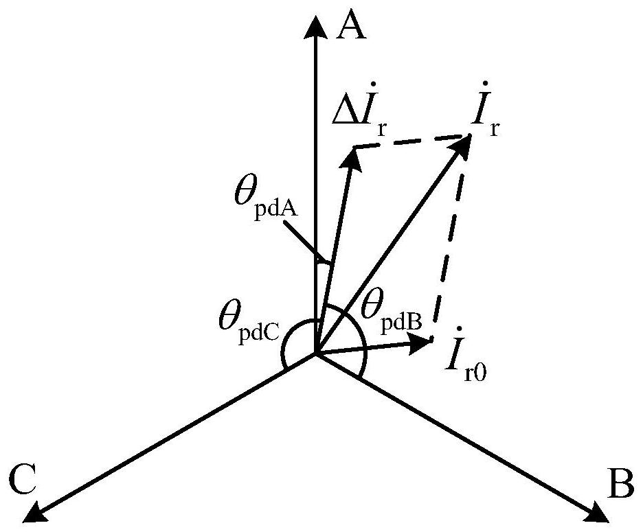
[0060] This embodiment is refined on the basis of the above-mentioned embodiments, image 3 is the protection principle phasor analysis diagram in the second embodiment of the present invention; Figure 4 is the phasor analysis diagram when the residual current phasor mutation in the third embodiment of the present invention is resistive; Figure 5 It is a phasor analysis diagram when the residual current phasor sudden change in the third embodiment of the present invention is capacitive.

[0061] Optionally, according to the real-time residual current and the residual current upstream of the protected zone two cycles ago, the residual current phasor mutation amount upstream of the protected zone is determined, including:

[0062] The sudden change of the residual current phasor upstream of the protected section is determined by subtracting the real-time residual current from the residual current phasor upstream of the protected section two cycles ago.

[0063] Exemplary, re...

Embodiment 3

[0087] This embodiment is refined on the basis of the above embodiments, and the specific method is as described in the above embodiments, which will not be repeated here.

[0088] Further, after the delay action of the leakage protection, it also includes:

[0089] Update the real-time residual current upstream of the protected section;

[0090] updating the residual current phasor mutation amount according to the updated real-time residual current;

[0091] Whether to return to the leakage protection is judged according to the updated residual current phasor mutation amount and a preset return value.

[0092] Further, the preset return value is 80% of the preset setting value.

[0093] Among them, after the leakage protection performs a delay action, the real-time residual current upstream of the protected section is updated Compare it with the monitoring quantity of 2 cycles before the fault Subtraction to obtain the phasor mutation amount of the upstream residual cur...


PUM


Abstract

The embodiment of the invention discloses a method and a device for judging leakage protection starting and delay action of a power grid. The method comprises the following steps: acquiring the real-time residual current of the upstream of a protected section; determining a residual current phasor break variable of the upstream of the protected section according to the real-time residual current and the residual current of the upstream of the protected section before two cycles; according to the amplitude of the residual current phasor break variable and a preset setting value, judging whether leakage protection is started or not; and judging whether leakage protection acts or not according to the phase difference between the phase of the residual current phasor break variable and the three-phase voltage. According to the embodiment of the invention, the residual current is reflected by using the amplitude of the residual current phasor break variable measured at the upstream of the protected section and the phase difference between the amplitude and the three-phase voltage, so that the leakage fault detection and protection are realized, and the leakage protection level and the leakage protection reliability of the low-voltage distribution network are improved.

Description

technical field [0001] Embodiments of the present invention relate to distribution network relay protection technology, and in particular to a method and device for judging start-up and delay action of leakage protection of a power grid. Background technique [0002] With the continuous expansion of the scale of the low-voltage distribution network, leakage faults are increasing, causing more personal electric shocks and electrical fire accidents; the rapid development of media communication has made leakage accidents spread rapidly and widely, resulting in many adverse social impacts. In the rainy season of 2020, many electric shock accidents caused by water accumulation in public power facilities occurred in Henan, Yunnan and other places in my country. After media reports, they aroused great public repercussions. According to statistics, in 2016, about 8,000 people died of electrocution nationwide, of which more than 85% occurred in the low-voltage distribution network, w...

Claims


Application Information

Patent Timeline
Patent Type & Authority Applications(China)
IPC IPC(8): H02H7/26H02H3/34H02H3/353H02H1/00
CPCH02H7/26H02H3/343H02H3/353H02H1/0007
Inventor 林志超罗步升张俊岭宋志坚丘桢坤朱灏章梁军华陈参宁徐大勇薛永端单玉凯孙荣可
Owner GUANGDONG POWER GRID CO LTD
Why Eureka
Try Eureka