
Patsnap Eureka
For R&D, Patsnap Eureka makes reading and utilizing patents & technical documents easy.
Patsnap Eureka AIR
Designed for self-driven R&D workflows. Generate viable solutions, solve complex R&D challenges, empower your innovation with AI.

Patsnap Eureka Materials
Designed for material experts only. Revolutionize your material R&D, from search, analyze, to developing new materials.

TechResearch
Generate reliable direction feasibility study reports for your R&D in just a few steps.

TechSeek
Discover and master advanced knowledge NOW. Basics, ideas, possibilities, all at once.

TechMind
As an expert in R&D Theories, TechMind can generates customized viable solutions instantly.

TechRisk
Analyze your overall solution with one click, know your potential R&D risks in advance.

TechMonitor
Get weekly tech updates, stay abreast of the latest tech innovations and key insights.
Backside illuminated TDI image sensor
An image sensor, back-illuminated technology, used in image communication, TV, color TV components, etc., can solve the problems of MTF decline, inconsistent charge distribution, affecting imaging quality, etc., to improve MTF, improve continuity, ensure The effect of image quality
- Summary
- Abstract
- Description
- Claims
- Application Information
AI Technical Summary
Problems solved by technology
Method used
Image

Examples
Embodiment Construction
[0016] To make the objectives, technical solutions and advantages of the present invention will become more apparent hereinafter in conjunction with the accompanying drawings and specific embodiments of the present invention will be further described in detail. It should be understood that the specific embodiments described herein are merely used to explain the present invention and are not intended to limit the present invention.
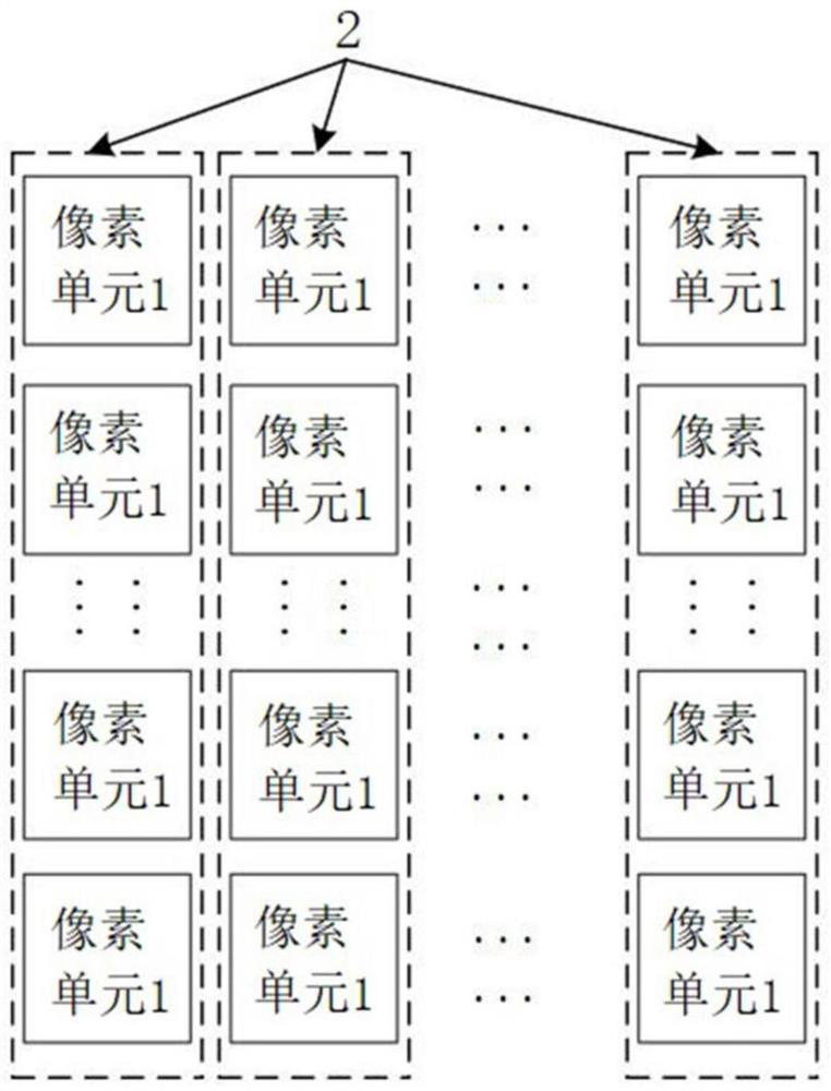
[0017] image 3 Shows the structure of a backside illuminated image sensor, a TDI embodiment of the present invention.
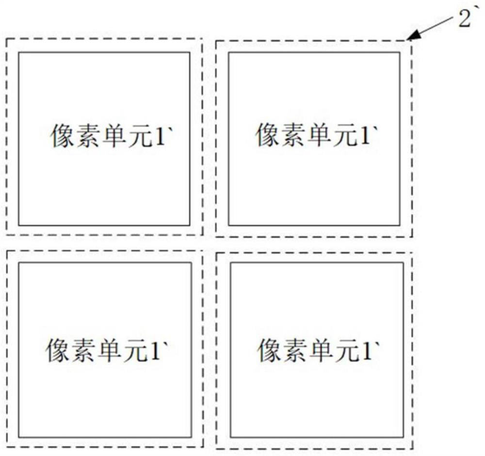
[0018] like image 3 Shown, back-illuminated TDI image sensor according to an embodiment of the present invention includes a pixel cell array, pixel unit array comprising at least one pixel unit, the structure of each pixel unit are the same.
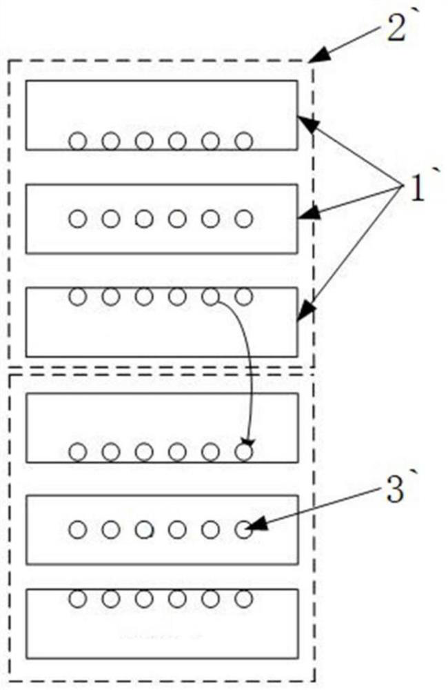
[0019] Pixel unit includes a set of control gate, the control gate comprises at least three control gate, a plurality of control gates are arranged in columns, to achieve transfer of charge int...
PUM
 Abstract
Description
Claims
Application Information
 - R&D Engineer
- R&D Manager
- IP Professional
- Industry Leading Data Capabilities
- Powerful AI technology
- Patent DNA Extraction
Browse by: Latest US Patents, China's latest patents, Technical Efficacy Thesaurus, Application Domain, Technology Topic, Popular Technical Reports.
© 2024 PatSnap. All rights reserved.Legal|Privacy policy|Modern Slavery Act Transparency Statement|Sitemap|About US| Contact US: help@patsnap.com