Mark printing equipment for relay manufacturing

A technology for printing equipment and relays, applied in printing, printing presses, rotary printing presses, etc., can solve the problems of inability to automatically clamp relays, inability to automatically, etc., and achieve the effect of stirring raw materials.

Inactive Publication Date: 2021-11-05
深圳市常润电子有限公司
View PDF0 Cites 0 Cited by
  • Summary
  • Abstract
  • Description
  • Claims
  • Application Information

AI Technical Summary

Problems solved by technology

[0005] In order to overcome the shortcomings of traditional relay brand printing equipment that cannot automatically clamp relays and automatically print relays, the present invention provides a brand printing equipment for relay manufacturing that can automatically clamp relays and automatically print relays

Method used


Image

  • Mark printing equipment for relay manufacturing
  • Mark printing equipment for relay manufacturing
  • Mark printing equipment for relay manufacturing

Examples


Embodiment Construction

[0040] In order to make the object, technical solution and advantages of the present invention clearer, the present invention will be further described in detail below in conjunction with the accompanying drawings and embodiments. It should be understood that the specific embodiments described here are only used to explain the present invention, not to limit the present invention.

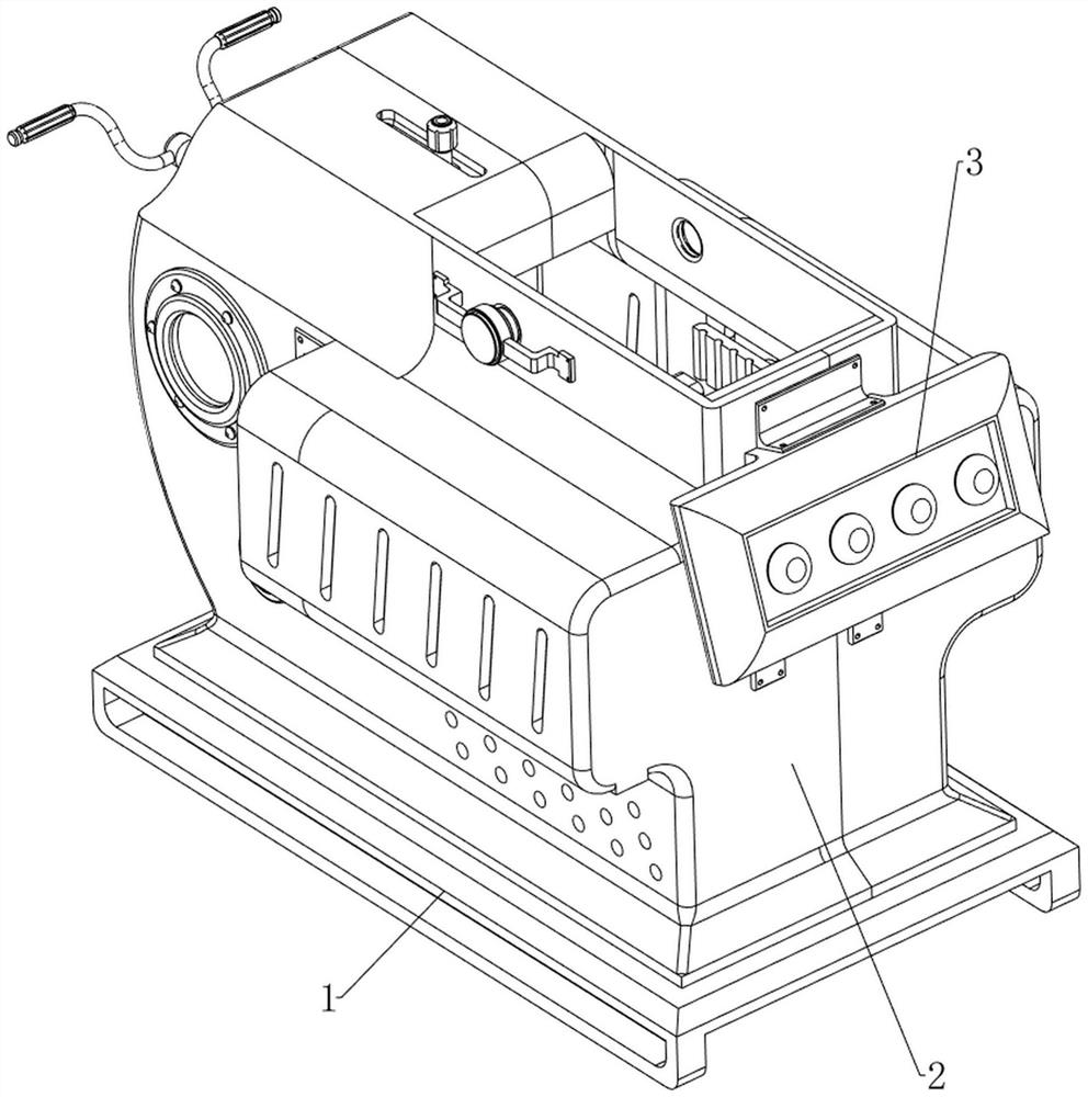
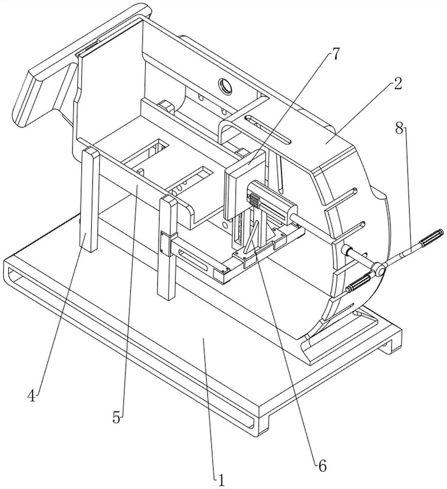
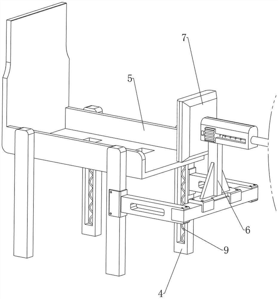
[0041] see Figure 1-Figure 20, the present invention provides a technical solution: a brand printing equipment for relay manufacturing, including a base 1, a frame body 2, a slide rail 4, a slide plate 5, a slide block 6, a first extrusion block 7, a push rod 8. The first spring 9, the second spring 10 and the clamping mechanism 11, the frame body 2 is welded on the base 1, two slide rails 4 are welded on the left and right sides of the inner wall of the frame body 2, and the upper sides of the four slide rails 4 The sliding plate 5 is connected between the two slide rails 4 on the rear side, and...


PUM


Abstract

The invention relates to printing equipment, in particular to mark printing equipment for relay manufacturing. According to the mark printing equipment for relay manufacturing, automatic relay clamping and automatic relay printing are achieved. The mark printing equipment for relay manufacturing comprises a base, a frame body, sliding rails, a sliding plate, a sliding block and the like. The frame body is arranged on the base, two sliding rails are arranged on each of the two sides of the inner wall of the frame body, the sliding plate used for bearing a relay is connected among the four sliding rails in a sliding mode, and the sliding block is connected between the middles of the two sliding rails on one side. After a second extrusion block moves to be in contact with the relay, the relay is clamped by the second extrusion block, so that position deviation of the relay in the printing process is prevented, and the effect that the relay is clamped by the second extrusion block is achieved.

Description

technical field [0001] The invention relates to a printing device, in particular to a designation printing device used for relay manufacturing. Background technique [0002] The nameplate on the relay housing is usually used to mark the brand name of the relay or the manufacturer, relay type and parameters and other information. The traditional relay nameplate is usually directly bonded or riveted on the relay housing. Once the nameplate is installed, only It can only be used on a specific type of relay, but the versatility is insufficient, and it is not convenient for users to adjust according to needs. [0003] The traditional relay nameplate printing method is to print the relay nameplate by the staff, and then paste the relay nameplate on the relay. In this process, due to the small size of the relay, the staff needs to use objects to fix the relay. To prevent the position of the relay from shifting, after the nameplate is pasted on the relay, the staff also needs to pr...

Claims


Application Information

Patent Timeline
IPC IPC(8): B41F17/24
CPCB41F17/24
Inventor 胡丽丽
Owner 深圳市常润电子有限公司
Why Eureka
Try Eureka