Battery lock and locking method

A battery lock and battery technology, which is applied in charging stations, electric vehicles, transportation and packaging, etc., can solve problems such as failure of connection parts to rotate, failure of battery lock, locking and unlocking, etc., and achieve the effect of precise rotation control

Pending Publication Date: 2021-11-05
SHENZHEN JINGZHI MACHINE
View PDF0 Cites 0 Cited by
  • Summary
  • Abstract
  • Description
  • Claims
  • Application Information

AI Technical Summary

Problems solved by technology

Then, during the rotation of the connecting piece, the rotation of the connecting piece may fail due to the existence of external resistance, and the inability to rotate to the preset angle will cause the locking or unlocking of the battery lock to fail

Method used


Image

  • Battery lock and locking method
  • Battery lock and locking method
  • Battery lock and locking method

Examples


Embodiment 1

[0055] Taking an electric truck as an example, the battery box is placed on the vehicle body of the electric truck. In order to prevent the battery box from moving on the vehicle body, a battery lock needs to be used to lock the battery box to the vehicle body. Existing battery locks generally screw the screw into the nut to lock the battery box. Due to the possible deviation in the placement of the battery box on the car body, there may be inaccurate butt joints of the thread heads when the threads are screwed together. As a result, the threads are worn during the screwing process, and even stagnation occurs, which prevents normal screwing, resulting in failure of locking.

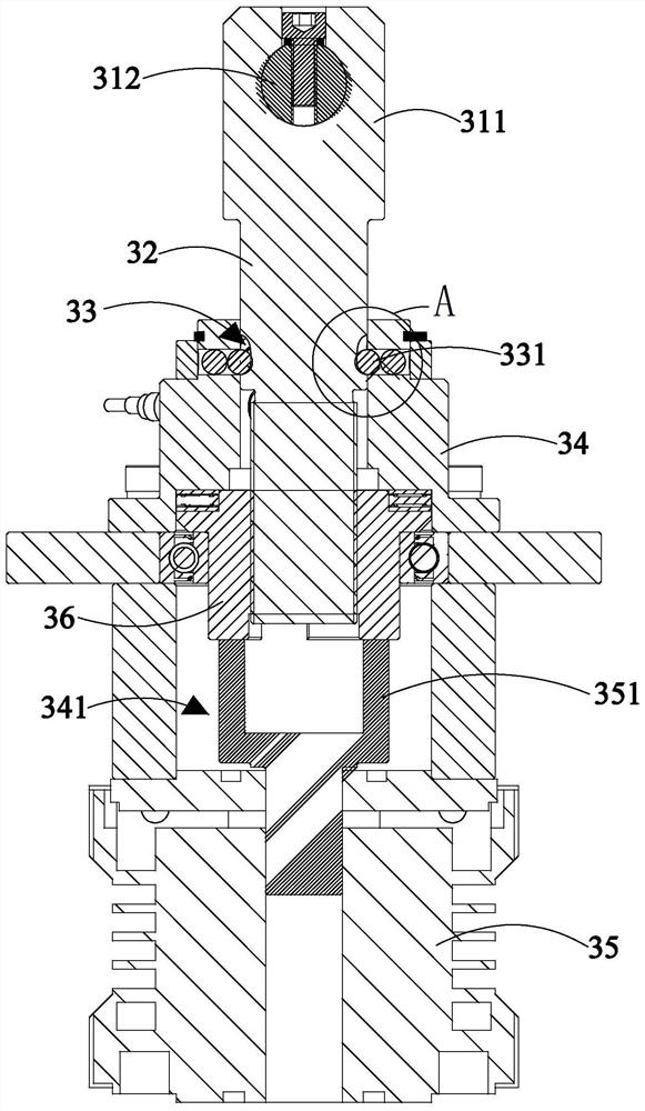
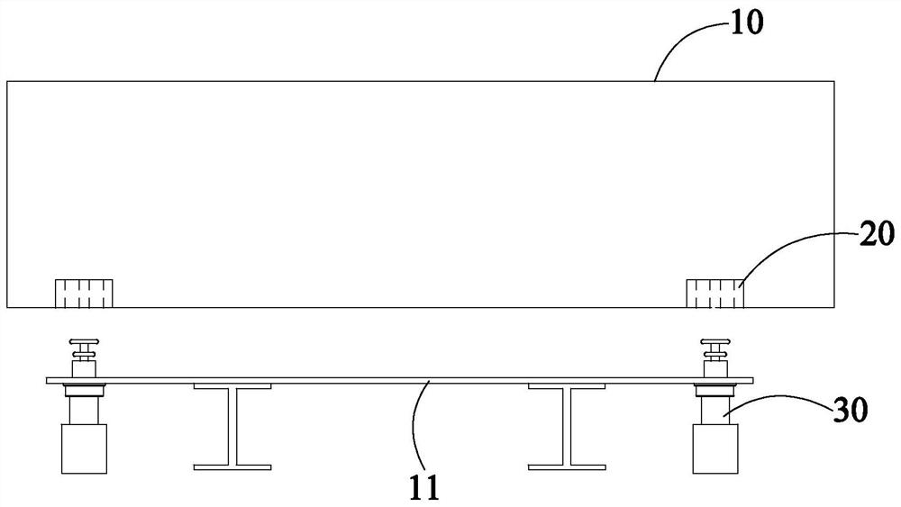
[0056] figure 1 It is a structural schematic diagram of Embodiment 1 of the battery lock in the power exchange system. Such as figure 1 As shown, the battery lock is used to lock the battery box 10 to the fixing part 11 , wherein the fixing part 11 can be a vehicle body, a battery rack or other parts fo...

Embodiment 2

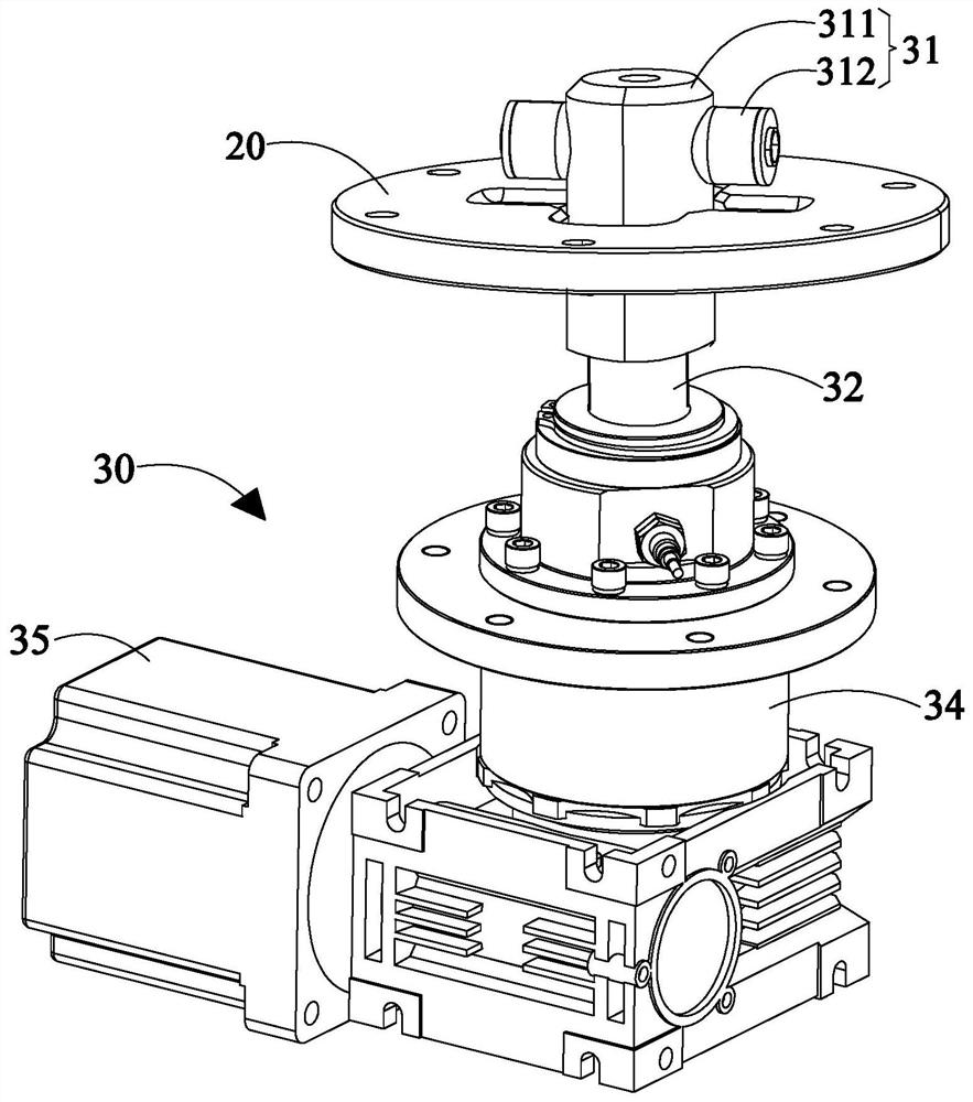
[0083] Figure 9 It is a schematic structural diagram of the battery lock in Embodiment 2, Figure 10 It is a schematic sectional structure diagram of the battery lock in embodiment 2. Such as Figure 9 with Figure 10 As shown, the difference between Embodiment 2 and Embodiment 1 lies in that the positions of the first clamping part and the second clamping part of the clamping assembly are reversed. In Embodiment 2, the entry channel 21 of the first clamping part and the bearing Part is connected to the connecting piece 32 of the lock body 30 . The structure of the first clamping member is the same as that of Embodiment 1, and will not be repeated here. Correspondingly, the second clamping member of the clamping assembly (ie Figure 9 T-bar structure shown) is connected to the lock head 20. Wherein, the structure of the second clamping member is the same as that of Embodiment 1, and will not be repeated here.

[0084] In addition, the difference between Embodiment 2 an...


PUM


Abstract

The invention relates to a battery lock and a locking method. The battery lock comprises a lock head; a lock body which comprises a connecting piece and a driving assembly, wherein the driving assembly is used for driving the connecting piece to move in the length direction; a clamping assembly which comprises a first clamping piece and a second clamping piece; a stop assembly which comprises a plug connector and a guide groove, wherein the guide groove comprises a curve section. According to the battery lock and the locking method, the guide groove and the plug connector are arranged on the stop assembly, the plug connector is embedded into the curve section of the guide groove, and when the driving assembly pulls the connecting piece to move in the length direction, the plug connector moves relative to the curve section to guide the connecting piece to rotate to the clamping position or the unlocking position, and the problem that the connecting piece is clamped by external force and cannot rotate to the preset position is solved.

Description

technical field [0001] The disclosure belongs to the field of battery swapping equipment for electric vehicles, in particular to a battery lock and a locking method. Background technique [0002] The statements in this section merely provide background technical information related to the present disclosure and do not necessarily constitute prior art. [0003] At present, the battery box of an electric vehicle needs to be firmly locked to the carrying area of ​​the electric vehicle, and the battery box must be unlocked or locked to the electric vehicle conveniently and quickly during automatic battery replacement. [0004] The existing battery lock can realize the clamping connection between the lock head and the lock body through the clamping piece, and then rotate the nut relative to the connecting piece, and pull the connecting piece to move along the length direction, thereby locking the battery box to the vehicle body. During the clamping process, the connecting part r...

Claims


Application Information

Patent Timeline
Patent Type & Authority Applications(China)
IPC IPC(8): B60L53/80
CPCB60L53/80Y02T10/70Y02T10/7072
Inventor 王伟王俊梁雄俊何忠祖赵伟李永昌温华锋
Owner SHENZHEN JINGZHI MACHINE
Why Eureka
Try Eureka