
Prism rotation adjustment mechanism, stepper exposure system, and stepper

a technology of rotation adjustment mechanism and exposure system, which is applied in the direction of microlithography exposure apparatus, mountings, instruments, etc., can solve the problems of limited control accuracy of piezoelectric ceramic motor, deviation of image plane from desired position, etc., to improve the rotation control accuracy of prisms, improve the rotation control accuracy, and control the rotational movement to be more accurate

Active Publication Date: 2021-08-31
SHANGHAI MICRO ELECTRONICS EQUIP (GRP) CO LTD
View PDF23 Cites 0 Cited by
  • Summary
  • Abstract
  • Description
  • Claims
  • Application Information

AI Technical Summary

Benefits of technology

The mechanism achieves higher prism rotation adjustment accuracy and eliminates crosstalk, enhancing image quality by allowing precise control of rotational movements with improved control accuracy and stability.

Problems solved by technology

During an exposure process carried out by an exposure system, deviations of an image plane from its desired position may arise from irregularities on the photomask surface (including those caused by machining errors and deformations from gravity and clamping) as well as from changes in the ambience.
In this technique, prism control accuracy of the objective adjustment mechanisms is dependent on, and thus limited by, control accuracy of the piezoelectric ceramic motor.

Method used


Image

  • Prism rotation adjustment mechanism, stepper exposure system, and stepper
  • Prism rotation adjustment mechanism, stepper exposure system, and stepper
  • Prism rotation adjustment mechanism, stepper exposure system, and stepper

Examples


Embodiment Construction

[0029]The present invention will be described in detail with reference to the accompanying drawings.

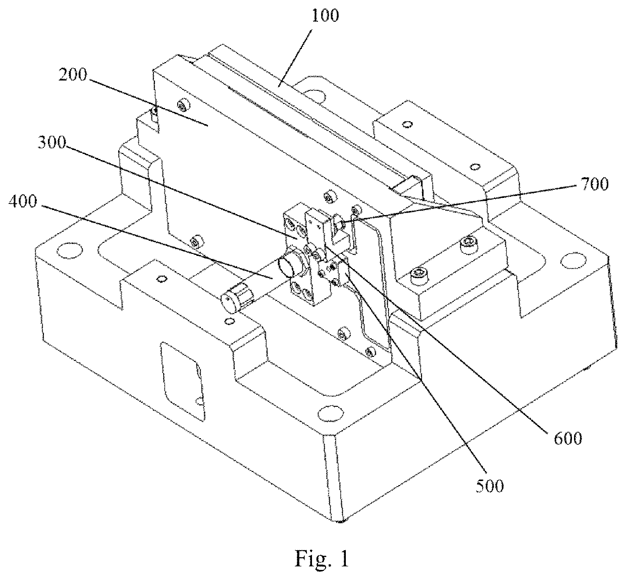
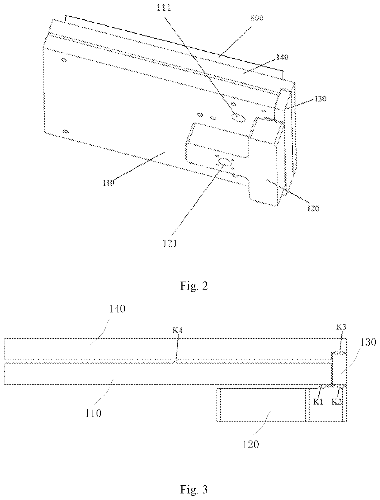
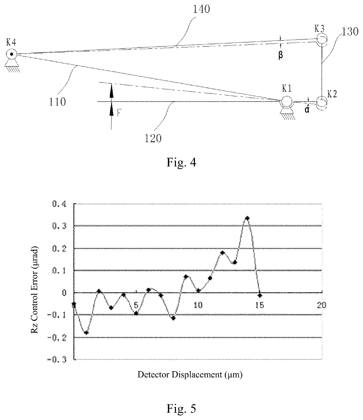
[0030]As shown in FIGS. 1 to 3, a prism 800 rotation adjustment mechanism according to the present invention includes a frame 200, a flexible mechanism 100 and an actuation mechanism. The flexible mechanism 100 includes a fixing component 110, an actuating component 120, a connecting component 130 and a swinging component 140, which are flexibly articulated together in a sequence. The fixing component 110, the actuating component 120, the connecting component 130 and the swinging component 140 are all block-shaped. The fixing component 110 is fixed to the frame 200. The actuation mechanism includes an actuator support 300 and an actuator unit 400 mounted on the actuator support 300. The actuator support 300 is fixed to the frame 200, and the actuator unit 400 is connected to the actuating component 120. The actuator unit 400 is implemented as a piezoelectric ceramic motor. One end of ...


PUM

PropertyMeasurementUnit
first-order mode frequencyaaaaaaaaaa
flexibleaaaaaaaaaa
gravityaaaaaaaaaa

Abstract

A prism rotation adjustment mechanism, a photolithographic exposure system and a photolithography tool are disclosed. The prism rotation adjustment mechanism includes a frame (200), a flexible mechanism (100) and an actuation mechanism. The flexible mechanism (100) includes a fixing component (110), an actuating component (120), a connecting component (130) and a swinging component (140) that are flexibly articulated in a sequence. The fixing component (110) is fixed to the frame (200). The actuation mechanism is fixed to the frame (200) and coupled to the actuating component (120). On the swinging component (140) are secured a prism wherein an axis of articulation between the swinging component (140) and the fixing component (110) is in correspondence with a rotational center of the prism. The flexible mechanism of the prism rotation adjustment mechanism is a quadrilateral flexibly-articulated assembly, in which, when driven by the actuation mechanism, the actuating component can convert translational movement into rotational movement, allowing the control of the rotational movement to be more accurate and hence improving the rotational control accuracy of the prisms. Moreover, the axis of articulation between the swinging component and the fixing component provides a stable axis for the prisms to rotate thereabout, avoiding crosstalk during the rotation and hence additionally improving the prism rotation control accuracy.

Description

TECHNICAL FIELD[0001]The present invention relates to photolithographic equipment and, in particular, to a prism rotation adjustment mechanism, a photolithographic exposure system and a photolithography tool.BACKGROUND[0002]Photolithography is a process to transfer a pattern from a photomask to a substrate by means of exposure. During this process, the substrate is supported on a workpiece stage and an exposure apparatus incorporated in a photolithography tool projects an image of the photomask pattern onto the surface of the substrate. Exposure is critical to the photolithography process and can be accomplished in a contact, proximity, projection or direct-write manner. Projection exposure is performed with an optical system for light convergence between the photomask and photoresist. Projection photolithography is of great significance to the fabrication of large-scale integrated circuits, in which the image transfer capabilities of the projection photolithography tools used are d...

Claims


Application Information

Patent Timeline
Patent Type & Authority Patents(United States)
IPC IPC(8): G02B7/18G03F7/20G02B7/00G02B5/04
CPCG02B7/1805G02B5/04G02B7/005G03F7/201G03F7/70225G03F7/70258G03F7/70825G03F7/709G02B7/18G03F7/20G03F7/70275
Inventor SU, TONGKE
Owner SHANGHAI MICRO ELECTRONICS EQUIP (GRP) CO LTD
Learn More