Electric operating mechanism of chassis truck

A technology of electric operating mechanism and chassis car, which is applied in the direction of electrical components, switchgear, pull-out switchgear, etc. It can solve the problems of potential safety hazards, inconvenient installation, broken and worn limit joints, etc., and achieves easy maintenance and maintenance. Eliminate potential safety hazards and achieve precise rotation control

Pending Publication Date: 2020-12-25
南京瑟维仕电气有限公司
View PDF0 Cites 0 Cited by
  • Summary
  • Abstract
  • Description
  • Claims
  • Application Information

AI Technical Summary

Problems solved by technology

The existing improvement point is to change the manual drive to the electric drive, that is, to change the handle rotation drive to the motor rotation drive, but the existing disadvantage is that the entire drive part is installed inside the central switch cabinet. On the one hand, it is inconvenient to install and affects the central switch cabinet. The internal layout structure has potential safety hazards. On the other hand, it is inconvenient to overhaul and the cost is high. At the same time, the limit joint used in conjunction with the manual rotation control handle is a circular structure. After long-term use, the manual rotation control handle will cause the limit joint Continuous wear, finer and finer, easy to break, and there are also problems of slipping after wear, etc., and manual control under special conditions cannot be realized (rotation control chassis car transmission square shaft)

Method used


Image

  • Electric operating mechanism of chassis truck
  • Electric operating mechanism of chassis truck
  • Electric operating mechanism of chassis truck

Examples


Embodiment Construction

[0029] The present invention will be further explained below in conjunction with the accompanying drawings and specific embodiments.

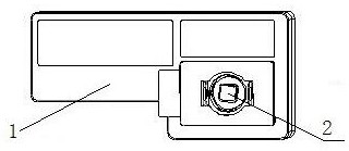
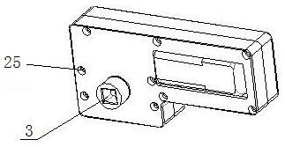
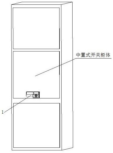
[0030] Such as Figure 1 to Figure 13 The chassis car electric operating mechanism shown is composed of a casing 1 arranged on the outer wall of the middle part of the switch cabinet and a driving assembly arranged in the casing 1; the driving assembly includes a motor mounting plate arranged in one end of the casing 1 5. The rear mounting plate 6, and the motor 4 arranged in the other end of the casing 1, and the outlet gear 7 arranged on the upper side of the motor mounting plate 5 and connected to the motor 4, and the two ends are respectively connected to the motor mounting plate 5, the rear The worm 9 connected to the upper mounting plate 6, the transmission spur gear 8 arranged at one end of the worm 9 and used in conjunction with the outlet gear 7, and the worm gear 8 arranged between the motor mounting plate 5 and the rear mounting plat...


PUM


Abstract

The invention belongs to the technical field of power switch cabinet application, and particularly discloses an electric operating mechanism of a chassis vehicle. The electric operating mechanism is composed of a shell arranged on the outer wall of the middle of a mid-set switch cabinet body and a driving assembly arranged in the shell. The electric operating mechanism of the chassis truck has thebeneficial effects that 1, the electric operating mechanism is reasonable in design structure, two control modes of a mid-set switch cabinet chassis truck are achieved, meanwhile, the two control modes (electric or manual) are switched conveniently and rapidly, and rotation control is accurate and stable; 2, the whole structure is installed on the outer wall of the mid-set switch cabinet, the layout structure of internal power components is not affected, and potential safety hazards are avoided; 3, the whole structure is installed on the outer wall of the mid-set switch cabinet, overhauling and maintenance are convenient, the manufacturing cost is low, installation is convenient, and time and labor are saved; and 4, the problems that the existing structure is matched with a manual rotarycontrol handle to use a limiting joint, and abrasion, breakage and the like are easy to occur are solved.

Description

technical field [0001] The invention belongs to the technical field of electric switchgear applications, and in particular relates to an electric operating mechanism of a chassis car, which is used for precise, stable, convenient and efficient control of the chassis car of a central switch cabinet, and improves the efficiency of inspection and maintenance. Background technique [0002] The switch cabinet is a kind of electrical equipment. The outside line of the switch cabinet first enters the main control switch in the cabinet, and then enters the sub-control switch, and each branch is set according to its needs. Such as instruments, automatic controls, motor magnetic switches, various AC contactors, etc., some also have high-voltage room and low-voltage room switch cabinets, high-voltage busbars, such as power plants, etc. load shedding. [0003] The main function of switchgear is to open and close, control and protect electrical equipment during the process of power gene...

Claims


Application Information

Patent Timeline
Patent Type & Authority Applications(China)
IPC IPC(8): H02B11/127H02B11/167
CPCH02B11/127H02B11/167
Inventor 焦驰
Owner 南京瑟维仕电气有限公司
Why Eureka
Try Eureka