Automatic fiber placement program operation control method
A technology of automatic silk laying and program operation, applied in the direction of program control, computer control, general control system, etc., can solve the problems of increasing the difficulty of equipment operators, increasing the risk of equipment operation, and being unable to adapt to automatic silk laying, so as to reduce manual participation Quantity, rapid re-laying, and the effect of improving laying efficiency
- Summary
- Abstract
- Description
- Claims
- Application Information
AI Technical Summary
Problems solved by technology
Method used
Image

Examples
Embodiment approach
[0035] This embodiment discloses an automatic silk laying program operation control method, as a basic implementation of the present invention, comprising the following steps:
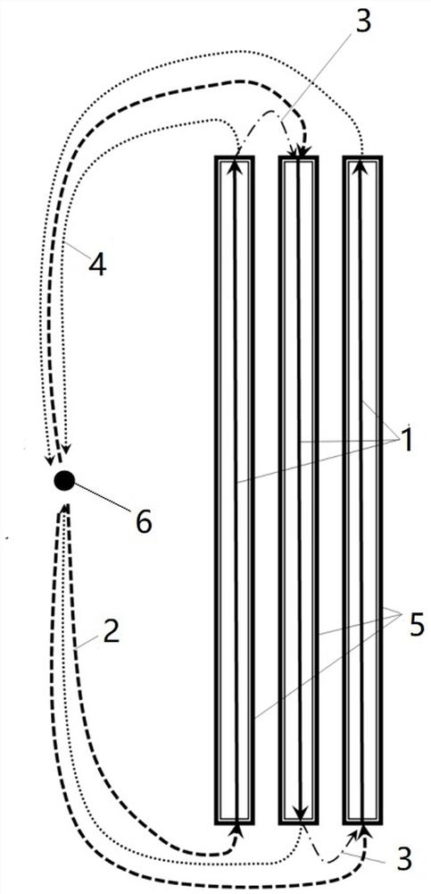
[0036] Step S1: Plan the automatic wire laying trajectory of the composite material, and generate several strips 5 for each layer, such as figure 2 As shown, four strips 5 are set, and each strip 5 includes the laying path 1 that must be passed by the automatic wire laying equipment to complete the laying of the strip 5;
[0037] Step S2: Establish the relative positional relationship between the laying model and the automatic laying equipment model, and set a fixed point in the equipment coordinate system as the safe laying point 6;
[0038] Step S3: For each strip 5, generate three non-interfering motion paths;
[0039] Step S4: NC program is set based on the laying path 1 in step S1, the laying safety parking point 6 in step S2 and the motion path in step S3;
[0040] Step S5: Carry out automatic...
Embodiment 2
[0043]This embodiment discloses an automatic silk laying program operation control method, as a preferred embodiment of the present invention, that is, in Example 1, the laying and laying safety mooring point 6 is far away from the laying model to ensure that the automatic silk laying equipment There is no interference between the laying safety berth point 6 and the laying model when it moves; in step S3, the three non-interfering motion paths are respectively: the outbound path 2, the laying safety berth point 6 to the starting point of laying path 1 return path 4, the movement path between the end point of laying path 1 and the laying safety berth point 6; transition path, the path between the end point of the current strip 5 laying path 1 and the starting point of the next strip 5 laying path 1 connection path, such as figure 2 shown.
[0044] Further, in step S4, the setting of the NC program includes setting the wire laying program, and setting the wire laying program i...
Embodiment 3
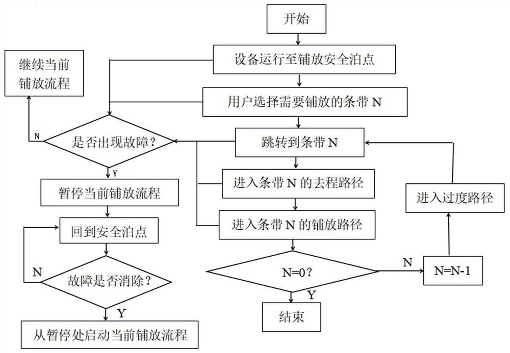
[0054] This embodiment discloses a method for controlling the operation of an automatic wire laying program. As a preferred embodiment of the present invention, that is, in Example 2, setting the NC program also includes setting a fault reset program, and setting the fault reset program includes the following steps:
[0055] Step S42-1, edit the NC code based on laying the safe parking point 6 and the motion path, including jumping to the logical control code of the return path 4, the strip 5 return path 4 program segment code and the interrupt program code;
[0056] Step S42-2, based on the NC code, setting the start mark of the program segment of the strip 5 return path 4.
[0057] Further, in step S5, the automatic wire laying part placement based on the NC program includes: starting the wire laying program, and judging in real time whether there is a wire laying fault during the running of the wire laying program, including the blockage detected by the equipment If there i...
PUM
 Abstract
Description
Claims
Application Information
 - Generate Ideas
- Intellectual Property
- Life Sciences
- Materials
- Tech Scout
- Unparalleled Data Quality
- Higher Quality Content
- 60% Fewer Hallucinations
Browse by: Latest US Patents, China's latest patents, Technical Efficacy Thesaurus, Application Domain, Technology Topic, Popular Technical Reports.
© 2025 PatSnap. All rights reserved.Legal|Privacy policy|Modern Slavery Act Transparency Statement|Sitemap|About US| Contact US: help@patsnap.com