
Heat dissipation structure of computer

A heat dissipation structure and computer technology, applied in computing, instruments, electrical and digital data processing, etc., can solve the problems of a single heat dissipation position of the integrated board, too many heat dissipation fans, poor heat dissipation effect, etc., and achieve direct heat dissipation and obvious air collection effect. , good heat dissipation effect

Pending Publication Date: 2021-11-05
广州鼎玉互联网有限公司
View PDF0 Cites 0 Cited by
  • Summary
  • Abstract
  • Description
  • Claims
  • Application Information

AI Technical Summary

Problems solved by technology

[0002] There will be a large number of integrated boards in the main box of the computer. In order to improve its service life, a cooling fan will be installed near the integrated board. If the cooling fan is located at the bottom of the integrated board, the exhaust gas will only act on the bottom of the integrated board. If If the cooling fan is located above the integrated board, the exhausted gas will only act on the upper side of the integrated board, so that the integrated board has a single cooling position and the cooling effect is poor. The noise is louder, and when the cooling fan is working, it will also generate a lot of heat

Method used


Image

  • Heat dissipation structure of computer
  • Heat dissipation structure of computer
  • Heat dissipation structure of computer

Examples


Embodiment Construction

[0019] The following is a clear and complete description of the technical solution of the new patent of the present invention in conjunction with the accompanying drawings. Apparently, the described embodiments are part of the embodiments of the present invention, rather than all of them. Based on the embodiments of the present invention, all other embodiments obtained by those skilled in the art without creative efforts fall within the protection scope of the present invention.

[0020] In the description of the present invention, it should be noted that if the terms "center", "upper", "lower", "left", "right", "vertical", "horizontal", "inner", "outer" appear The orientation or positional relationship indicated by etc. is based on the orientation or positional relationship shown in the drawings, and is only for the convenience of describing the present invention and simplifying the description, rather than indicating or implying that the referred device or element must have a...


PUM


Abstract

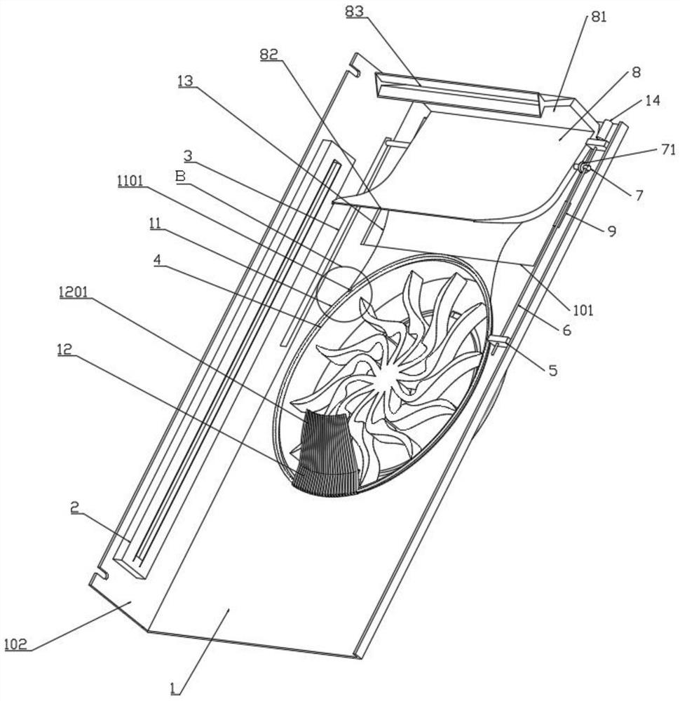
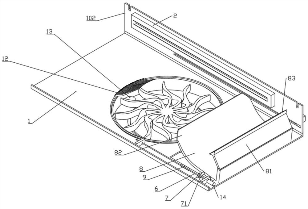
The invention provides a heat dissipation structure of a computer which comprises an aluminum alloy heat dissipation seat with a heat dissipation fan in the middle, a screw located on the outer side of the heat dissipation fan is installed on the aluminum alloy heat dissipation seat through a bearing seat, and a displacement rod capable of moving in the axis direction of the screw along with rotation of the screw is arranged on the screw. An air guide seat is arranged in the middle of the displacement rod, a rack located on the rear side of the screw rod is arranged on the aluminum alloy heat dissipation seat, a gear is arranged on the displacement rod, and the air guide seat is arranged on one side of the heat dissipation fan in a screw rod driving mode, so that the heat dissipation fan can dissipate heat of the integrated board upwards from the bottom, the air guide seat can move to the position close to the heat dissipation fan to collect and utilize part of exhausted air to dissipate heat downwards from the top of the integrated board. Therefore, for components installed on the upper surface of the integrated board, the heat dissipation mode is more direct, and the heat dissipation effect is better.

Description

technical field [0001] The invention relates to the technical field of computer heat dissipation, in particular to a computer heat dissipation structure. Background technique [0002] There will be a large number of integrated boards in the main box of the computer. In order to improve its service life, a cooling fan will be installed near the integrated board. If the cooling fan is located at the bottom of the integrated board, the exhaust gas will only act on the bottom of the integrated board. If If the cooling fan is located above the integrated board, the exhausted gas will only act on the upper side of the integrated board, so that the integrated board has a single cooling position and the cooling effect is poor. The noise is loud, and when the cooling fan is working, it will also generate a lot of heat. Contents of the invention [0003] The technical problem to be solved by the present invention is to provide a heat dissipation structure for a computer, in which h...

Claims


Application Information

Patent Timeline
IPC IPC(8): G06F1/20G06F1/18
CPCG06F1/20G06F1/206G06F1/183
Inventor 肖池国
Owner 广州鼎玉互联网有限公司
Learn More