

Industrial robot spraying head mounting mechanism and using method thereof
A technology of industrial robots and installation mechanisms, which is applied in the direction of spraying devices, manipulators, manufacturing tools, etc. It can solve the problems of inconvenient adjustment of the spraying angle of the spraying head and the inability to meet the spraying operation of the spraying robot, so as to avoid being blocked and meet the spraying requirements.
- Summary
- Abstract
- Description
- Claims
- Application Information
AI Technical Summary
Problems solved by technology
Method used
Image

Examples
Embodiment 1
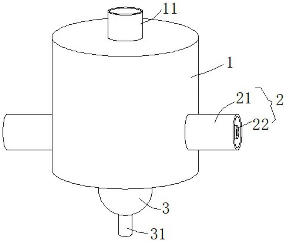
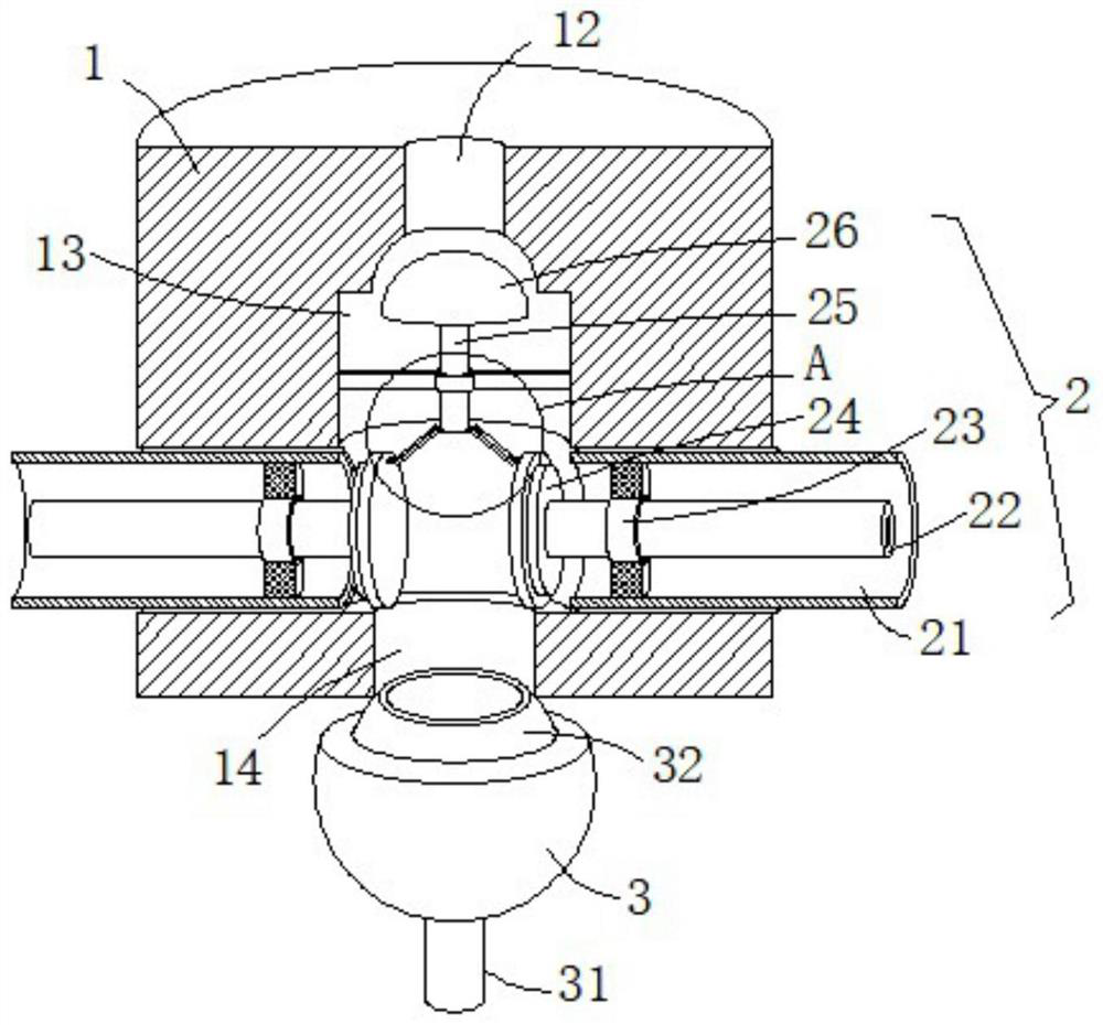
[0027] see Figure 1 to Figure 3 , the present embodiment provides an installation mechanism for an industrial robot spraying head and a method of use thereof, including a mounting base 1 and a spherical sealing block 32, the top end of the mounting base 1 is provided with a connecting hole 12, and the opening of the connecting hole 12 is provided with a second A threaded connection head 11, the mounting seat 1 is plugged with the spraying outlet of the robot through the first threaded connection head 11, the mounting seat 1 is connected with the spraying outlet of the robot, and the mounting seat 1 is used as a mounting part, and the spraying liquid can be sprayed from the first screw thread The connector head 11 is introduced into the connection hole.
[0028] The inside of the mounting seat 1 is axially provided with an adjusting cavity 13 communicating with the connecting hole 12, the spraying liquid can be introduced into the adjusting cavity 13 through the connecting hol...
Embodiment 2
[0035] see Figure 4 , further improvements have been made on the basis of Example 1:
[0036]The tip of the arc-shaped stainless steel shrapnel 33 is fixed with a fluororubber sheet attached to the outer wall of the spherical sealing block 32. By fixing the fluororubber sheet at the tip of the arc-shaped stainless steel shrapnel 33 and adhering to the outer wall of the spherical sealing block 32, the use of fluororubber The anti-slip characteristics of the sheet increase the frictional force when it contacts the outer wall of the spherical sealing block 32, and avoid the phenomenon that the arc-shaped stainless steel shrapnel 33 slides freely on the outer wall of the spherical sealing block 32, thereby preventing the spherical rotating seat 3 from surrounding the spherical sealing Block 32 outer walls rotate at will.
Embodiment 3
[0038] see Figure 1-3 , a further improvement has been made on the basis of Embodiment 1: In a further embodiment, the side wall of the mounting seat 1 is provided with a conduction mechanism 2, which is connected to the high-pressure water gun through the conduction mechanism 2, and is used to conduct the water blocked by impurities. No need to disassemble the spray head.
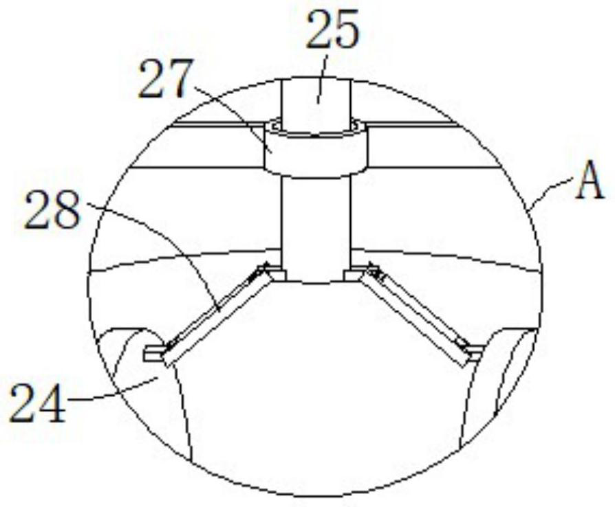
[0039] The conduction mechanism 2 includes two threaded sleeves 21, which are symmetrically fixed and inserted on the radial side wall of the mounting seat 1. The inside of the threaded sleeves 21 communicates with the inside of the adjustment cavity 13, and the threaded sleeves 21 21 realizes that the adjustment cavity 13 communicates with the outside, and one end of the threaded sleeve 21 close to the adjustment cavity 13 is fixedly installed with a threaded sleeve 23 through a support frame, and the threaded sleeve 23 is inserted with a threaded adjustment rod 22 through a threaded hole. One end of th...
PUM
 Abstract
Description
Claims
Application Information