
Eureka
For R&D, Eureka makes reading and utilizing patents & technical documents easy.
Eureka AIR
Designed for self-driven R&D workflows. Generate viable solutions, solve complex R&D challenges, empower your innovation with AI.

Eureka Materials
Designed for material experts only. Revolutionize your material R&D, from search, analyze, to developing new materials.

TechResearch
Generate reliable direction feasibility study reports for your R&D in just a few steps.

TechSeek
Discover and master advanced knowledge NOW. Basics, ideas, possibilities, all at once.

TechMind
As an expert in R&D Theories, TechMind can generates customized viable solutions instantly.

TechRisk
Analyze your overall solution with one click, know your potential R&D risks in advance.

TechMonitor
Get weekly tech updates, stay abreast of the latest tech innovations and key insights.
In-vitro forging elastic box and in-vitro forging auxiliary tool
A technology of elastic boxes and auxiliary tools, which is applied in the direction of manufacturing tools, forging presses, forging presses, etc., can solve the problems of short service life of super-large forging presses, reduce shaking and tilting, prolong service life, and ensure stable movement sexual effect
- Summary
- Abstract
- Description
- Claims
- Application Information
AI Technical Summary
Problems solved by technology
Method used
Image

Examples
Embodiment 1
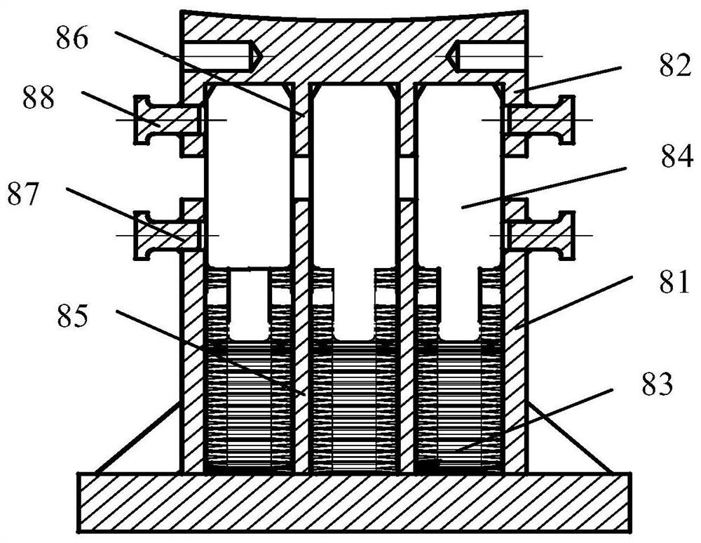
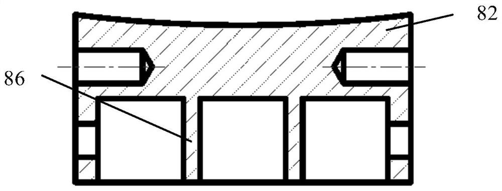
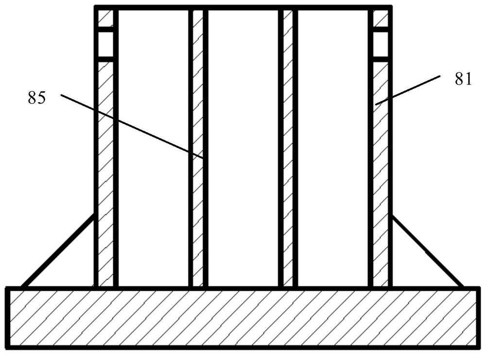
[0075] This embodiment provides an in vitro forged elastic box, see Figure 1 to Figure 5 , comprising box body 81, case cover 82, spring 83 (for example, spring 83 comprises a plurality of disc springs arranged axially along spring 83, and a plurality of disc springs constitute a set of spring 83) and guide post 84, guide post 84 One end of the beam body is supported on the bottom of the box body 81 by a spring 83, and the box cover 82 is set on the other end of the guide column 84. There is a gap between the box body 81 and the box cover 82, and the side of the beam body 1 close to the blank is defined as the forging side. , the other side of the beam body 1 is the non-forging side, that is to say, the box body 81 is arranged on the mounting surface of the forging equipment, and the non-forging side of the beam body 1 of the in vitro forging aid is supported on the box cover 82 .
[0076] During implementation, the box cover 82 is supported on the box body 81 by the spring 8...
Embodiment 2
[0088] This embodiment provides an in vitro forging aid, see Figure 6 to Figure 7, including the beam body 1 and the in vitro forged elastic box provided in Embodiment 1, one end of the beam body 1 is a non-forged side, and the non-forged side of the beam body 1 is supported on the box cover 82 .
[0089] Compared with the prior art, the beneficial effects of the external forging auxiliary device provided in this embodiment are basically the same as those of the external forging elastic box provided in Embodiment 1, and will not be repeated here.
[0090] Exemplarily, the above-mentioned in vitro forging aids can be used in processes such as in vitro widening, in vitro hole expansion, in vitro shaping or in vitro expansion of super-large tube sheets.
[0091] From the perspective of moment balance, the position of the connection between the movable beam 4 and the beam body 1 adopts an adjustable structure, for example, it can be located at the midpoint between the forged side...
PUM
 Abstract
Description
Claims
Application Information
 - R&D Engineer
- R&D Manager
- IP Professional
- Industry Leading Data Capabilities
- Powerful AI technology
- Patent DNA Extraction
Browse by: Latest US Patents, China's latest patents, Technical Efficacy Thesaurus, Application Domain, Technology Topic, Popular Technical Reports.
© 2024 PatSnap. All rights reserved.Legal|Privacy policy|Modern Slavery Act Transparency Statement|Sitemap|About US| Contact US: help@patsnap.com