Supercharge Your Innovation With Domain-Expert AI Agents!

Electronic mechanical lock

An electro-mechanical and housing technology applied to electro-mechanical locks. It can solve the problems of criminals opening, poor practicability, and low purely mechanical safety, and achieve the effect of increasing safety.

Active Publication Date: 2021-11-09
AIR FORCE UNIV PLA
View PDF6 Cites 0 Cited by
  • Summary
  • Abstract
  • Description
  • Claims
  • Application Information

AI Technical Summary

Problems solved by technology

[0002] Locks are things that are often used in life, and people's demand for locking is increasing. There are more and more types of locks on the market. Now, electronic mechanical locks are more commonly used. Electronic mechanical locks have the characteristics of high safety, but general electronic locks Most of the mechanical locks are used on the gate and installed together with the door, and there are few electronic mechanical locks that can be used alone. Most of the locks used alone are purely mechanical, and the safety of pure machinery is not high. It is easy for criminals to use other tools to open
[0003] A Chinese patent discloses an electromechanical lock (authorized notification number CN205617939U). The electromechanical padlock of this patent technology can realize keyless unlocking. It adopts a rotating structure driven by a motor to cooperate with a shaft assembly and a rotor assembly. It is reliable and has low power consumption. However, the modified patent does not have the function of manual unlocking, and the practicability is not strong. Electronic products are not perfect and there will always be problems. When the internal circuit of the lock has problems or the power is insufficient, the modified patented lock cannot be opened without a key.

Method used


Image

  • Electronic mechanical lock
  • Electronic mechanical lock
  • Electronic mechanical lock

Examples


Embodiment 1

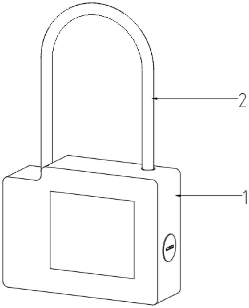
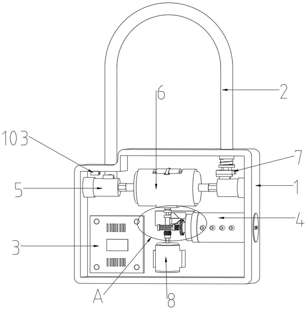
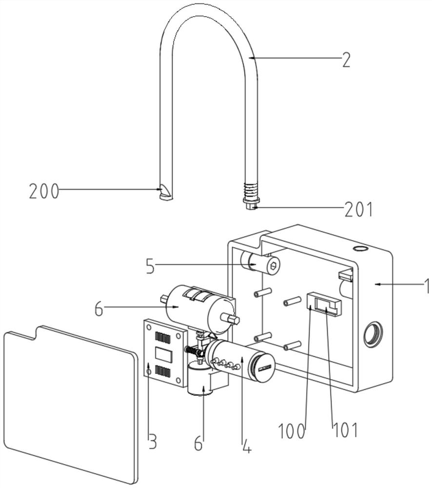
[0035] see figure 1 , 2 , 3, 5, 6, 8, 9, 11, in an embodiment of the present invention, an electromechanical lock includes a housing 1, a lock beam 2 and a key 110, the front end of the housing 1 is provided with an operation panel, and the housing 1 The interior of the housing is detachably connected with a control board 3, which is provided with a buzzer, and the interior of the housing 1 is detachably connected with a motor 8, and a rubber pad is provided between the motor 8 and the housing 1, and the rubber pad and the housing 1. It is fixedly connected, and the rubber can act as a shock absorber. There is a battery on the right side of the motor 8. The inside of the housing 1 is located above the motor 8 and is detachably connected with an unlocking structure. The left and right side walls inside the housing 1 are movable. Connect the limit head 5, the limit head 5 is located on the left and right sides of the unlocking structure, and the center of the limit head 5 and t...

Embodiment 2

[0038] see Figure 4 , combined with the basis of Embodiment 1, the right end of the housing 1 is provided with a lock hole, and the housing 1 is also provided with a lock core, the lock core includes a fixed shell 4, the fixed shell 4 and the lock hole are on the same straight line, and the fixed shell 4 It is fixedly connected with the shell 1, and the shell wall of the fixed shell 4 is fixedly connected with several electromagnet columns 400. The number of the electromagnet columns 400 is set to eight, and four of the eight electromagnet columns 400 are located on the front side of the fixed shell 4. , the other four are located at the rear side of the fixed shell 4, the electromagnet column 400 all runs through the shell wall of the fixed shell 4, the inside of the fixed shell 4 is movably connected with a rotating sleeve 401, and the left end of the rotating sleeve 401 is provided with a polygonal short bar (in the figure As shown), the right side of the rotating sleeve 4...

Embodiment 3

[0040] see Figure 7 , combined with the basis of Embodiments 1 and 2, the transmission structure includes a second rotating rod 612, the second rotating rod 612 is on the same straight line as the first rotating rod 608, and one end of the second rotating rod 612 is provided with a second friction disc 614, The other end is provided with connecting block 616, and the upper end of second friction disc 614 is provided with rubber ring equally, and the upper end of second friction disc 614 is fixedly connected with inserting rod 615, and inserting rod 615 is set to polygon, and inserting rod 615 and first rotating Corresponding to the polygonal groove at the lower end of the rod 608, the insertion rod 615 is inserted in the polygonal groove at the lower end of the first rotating rod 608, and the insertion rod 615 is slidingly connected with the first rotating rod 608, and the middle part of the second rotating rod 612 is movably connected with The second push plate 613, the midd...


PUM


Abstract

The invention discloses an electronic mechanical lock and belongs to the field of locks. The electronic mechanical lock comprises a shell, a lock beam and a key, a motor is detachably connected in the shell, an unlocking structure is detachably connected to the position, located above the motor, in the shell, and limiting heads are movably connected to the left side wall and the right side wall in the shell. During use, when a left rotating head moves leftwards, a connector can penetrates into the left limiting head, then the connector drives the limiting head to rotate, and therefore a protruding block is separated from a gap on the lock beam, but the lock beam cannot rotate at the moment, the lock cannot be opened, then a right connector is inserted into the right limiting head to drive the limiting head to rotate through rotation of the motor, a protruding head is stirred through the protruding block when the limiting head rotates, a first clamping plate and a second clamping plate are separated, after the first clamping plate and the second clamping plate are separated, the lock can be opened by rotating the lock beam, in this way, the lock can be opened only through two working procedures, and then the safety of the lock is improved.

Description

technical field [0001] The invention relates to the field of locks, in particular to an electromechanical lock. Background technique [0002] Locks are things that are often used in life, and people's demand for locking is increasing. There are more and more types of locks on the market. Now, electronic mechanical locks are more commonly used. Electronic mechanical locks have the characteristics of high safety, but general electronic locks Most of the mechanical locks are used on the gate and installed together with the door, and there are few electronic mechanical locks that can be used alone. Most of the locks used alone are purely mechanical, and the safety of pure machinery is not high. It is easy for criminals to use other tools to open . [0003] A Chinese patent discloses an electromechanical lock (authorized notification number CN205617939U). The electromechanical padlock of this patent technology can realize keyless unlocking. It adopts a rotating structure driven ...

Claims


Application Information

Patent Timeline
Patent Type & Authority Applications(China)
IPC IPC(8): E05B49/00
CPCE05B49/00E05B49/002
Inventor 齐汝铭张佳丽高鹏曾番王庆力张世龙
Owner AIR FORCE UNIV PLA
Features
  • R&D
  • Intellectual Property
  • Life Sciences
  • Materials
  • Tech Scout
  • Unparalleled Data Quality
  • Higher Quality Content
  • 60% Fewer Hallucinations
Learn More