Quick assembly type tool rod body connecting structure
A technology of connecting structure and tool rod, applied in the direction of rod connection, connecting member, manufacturing tool, etc., can solve problems such as affecting the assembly and use of tools, damage to connecting parts, inability to achieve quick installation and simple assembly, etc., to ensure strength and stability. Sexual, easy-to-use effects
- Summary
- Abstract
- Description
- Claims
- Application Information
AI Technical Summary
Problems solved by technology
Method used
Image
Examples
Embodiment 1
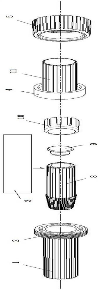
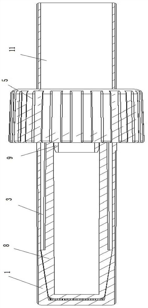
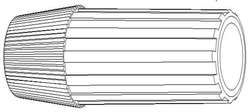
[0038] The connection structure is used to connect the rod body to the rod body. This structure also includes a connecting pipe 11. The free ends of the outer sleeve 1 and the connecting pipe 11 are cylindrical pipe bodies. The length of this part of the pipe body is adjusted according to actual needs to match different length requirements. The tool is also connected through the connection structure between the rod body and the rod body. Such as figure 2 As shown, two adjacent rod bodies are connected through this connection structure, and the outside of the connecting pipe and the outer sleeve is set according to the actual length of the tool rod body, or the tool rod body is connected to the outside by gluing or injection molding. See attached for specific structure Figure 1-8 .
[0039] In this embodiment, the reinforced limit assembly includes a metal pipe 3 and a connecting pipe 11 . One end of the metal tube 3 is set outside the inner sleeve 8 ; the inner sleeve 8 w...
Embodiment 2
[0044] The connecting structure is used for connecting the rod body with the tool head. The outer surface of the outer sleeve is a tapered structure matching the connecting pants of the tool head, see attached Figure 9-15 .
[0045] In this embodiment, the reinforced limiting assembly includes a metal tube 3 , a fiber tube 6 , a limiting sleeve 4 and a positioning pin 7 . The metal 3 tube is a hollow cylindrical tube, one end of which is sleeved in the inner sleeve 8, and the outside of the other end is sleeved with the fiber tube 6; In this embodiment, the fiber tube and the spacer sleeve are separate structures. Preferably, the outer wall of the fiber tube and the inner wall of the spacer sleeve are provided with matching spacer teeth; the two can also be an integral structure of injection molding. The limit sleeve 4 is used in conjunction with the fastening sleeve 5, and the end of the fastening sleeve is provided with an annular end face, which acts as a limit to the li...
PUM
 Abstract
Description
Claims
Application Information
 - R&D
- Intellectual Property
- Life Sciences
- Materials
- Tech Scout
- Unparalleled Data Quality
- Higher Quality Content
- 60% Fewer Hallucinations
Browse by: Latest US Patents, China's latest patents, Technical Efficacy Thesaurus, Application Domain, Technology Topic, Popular Technical Reports.
© 2025 PatSnap. All rights reserved.Legal|Privacy policy|Modern Slavery Act Transparency Statement|Sitemap|About US| Contact US: help@patsnap.com


