
Clip-on ammeter

A clamp-type ammeter and ammeter technology, applied in the field of ammeters, can solve problems such as troublesome use and the inability of users to press the wrench.

Pending Publication Date: 2021-11-09
盛缪钰
View PDF1 Cites 2 Cited by
  • Summary
  • Abstract
  • Description
  • Claims
  • Application Information

AI Technical Summary

Problems solved by technology

[0004] The existing clamp-on ammeter has some disadvantages in use: when the clamp-on ammeter is in use, it is necessary to press the wrench to open the clamp head, and the measuring height is higher than the height of the user, and there is no advantage for the user to climb, and it is in a tight When the internal current of the wire is in the state, the user cannot press the wrench, which is troublesome to use. In order to solve the above problems, we propose a clamp ammeter

Method used


Image

  • Clip-on ammeter
  • Clip-on ammeter
  • Clip-on ammeter

Examples


Embodiment approach

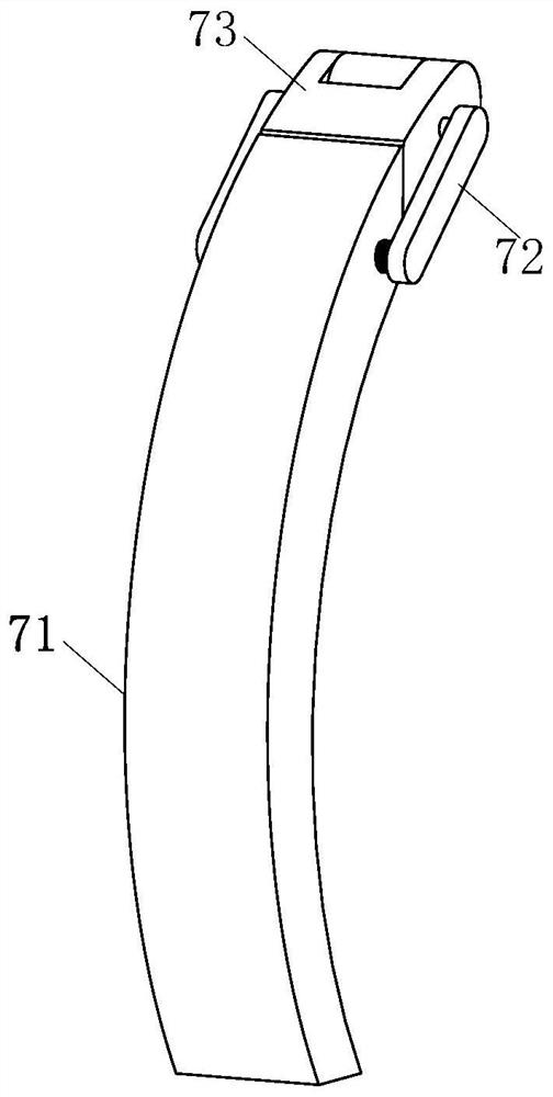
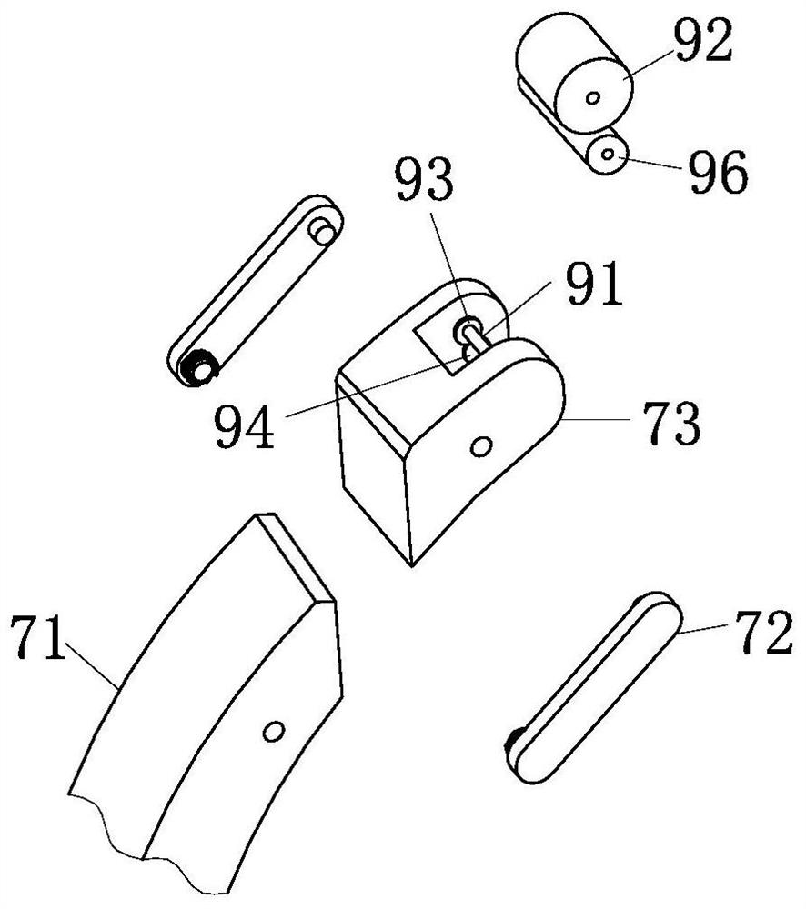
[0026] As an embodiment of the present invention, the wire dredging mechanism 9 further includes a driving pulley 93, the driving pulley 93 is arranged at the end of the first rotating shaft 91, and the driving pulley 93 is connected with a The driven pulley 94, the driven pulley 94 is connected to the U-shaped groove through the cavity rotating shaft 95, and the cleaning secondary roller 96 is fixedly sleeved on the cavity rotating shaft 95, and the cleaning secondary roller 96 is located on the pulley 92, the outer wall of the cleaning auxiliary roller 96 is provided with a plurality of cleaning scrapers 97 obliquely, and the tilting rotation direction and detection guide of the plurality of cleaning scrapers 97 enter the inside of the first pincer head 71 and the second pincer head 8 When the pulley 92 rotates in the same direction; during work, when the pulley 92 is in contact with the electric wire to rotate itself, the first rotating shaft 91 will drive the driving pulley...


PUM


Abstract

The invention discloses a clip-on ammeter which comprises an ammeter body, one side of the ammeter body is rotatably connected with a wrench, the front end of the ammeter body is provided with a display screen, a switch is arranged the display screen at the front end of the ammeter body, and the lower end of the ammeter body is provided with a telescoping mechanism. The lower end of the telescoping mechanism is connected with a handle, the upper end of the ammeter body is provided with a clamping mechanism, the clamping mechanism comprises a first clamp head, the upper end of the first clamp head is rotatably connected with a rotating head, the rotating head is internally provided with a first rotating shaft, and the outer side of the first rotating shaft is provided with a pulley. The front end of the first clamp head is provided with a rotating mechanism, the rotating mechanism comprises a rotating rod, and the position, close to the upper end, of the rear end of the rotating rod is connected with a fixing rod. The clip-on ammeter is simple in structure, convenient to operate and capable of conveniently measuring the current of an electric wire at a high position.

Description

technical field [0001] The invention relates to the technical field of ammeters, in particular to a clamp ammeter. Background technique [0002] The clamp ammeter is composed of a current transformer and an ammeter. The iron core of the current transformer can be opened when the wrench is squeezed tightly. After the wrench is opened, the iron core is closed, and the measured circuit wire passing through the iron core becomes the primary coil of the current transformer, and the current is induced in the secondary coil through the current, so that the ammeter connected to the secondary coil has an indication to measure The current of the circuit under test. [0003] The invention patent with the application number: CN209043968U2 discloses a clamp-on ammeter, which relates to the field of current measurement. The elastic part for reset; the inside of the ammeter housing is provided with a cavity, the elastic part is arranged in the cavity, and the top of the adjustable wrench...

Claims


Application Information

Patent Timeline
Patent Type & Authority Applications(China)
IPC IPC(8): G01R19/00G01R1/04
CPCG01R19/00G01R1/04
Inventor 盛缪钰许青华
Owner 盛缪钰
Learn More