Power cable bridge manufacturing and forming processing technology

A cable tray and forming processing technology, which is applied in the direction of manufacturing tools, metal processing equipment, electrical components, etc., can solve the problems of power cable tray offset, poor practicability, and drilling deviation, so as to improve the clamping stability and practicality. sex, the effect of avoiding offset

Active Publication Date: 2021-11-09
深圳市熊猫眼通讯科技有限公司
View PDF5 Cites 0 Cited by
  • Summary
  • Abstract
  • Description
  • Claims
  • Application Information

AI Technical Summary

Problems solved by technology

[0003] The existing cables are mixed and stacked together, and they tend to heat up after power on. When the heat reaches a certain level, the cables catch fire, which poses a great safety hazard. It can also fix the power cable bridge. The existing power cable bridge drilling process is mainly through manually holding the power cable bridge, placing it in the processing area of ​​the punching equipment, and then punching the surface of the power cable bridge through the punching equipment. , such a power cable tray manufacturing process is very simple and common, but there are still the following problems:
[0004] (1) The existing power cable tray has poor stability after being clamped and fixed before drilling, which further leads to the deviation of the power cable tray after being subjected to external force during the drilling operation, resulting in Deviation in punching
[0005] (2) The existing power cable bridges cannot accurately locate the positions of the holes during processing, which may easily cause the spacing between each hole to be different, which seriously affects the aesthetics of the power cable bridges. At the same time, the existing equipment only It is possible to drill holes for one size of power cable tray, and the practicability of the equipment is poor

Method used


Image

  • Power cable bridge manufacturing and forming processing technology
  • Power cable bridge manufacturing and forming processing technology
  • Power cable bridge manufacturing and forming processing technology

Examples


Embodiment Construction

[0041] The following will clearly and completely describe the technical solutions in the embodiments of the present invention with reference to the accompanying drawings in the embodiments of the present invention. Obviously, the described embodiments are only some, not all, embodiments of the present invention. Based on the embodiments of the present invention, all other embodiments obtained by persons of ordinary skill in the art without making creative efforts belong to the protection scope of the present invention.

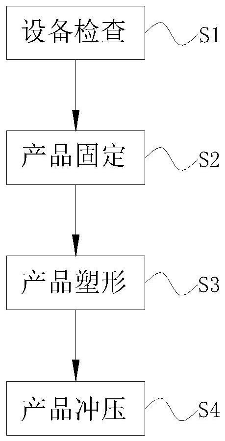
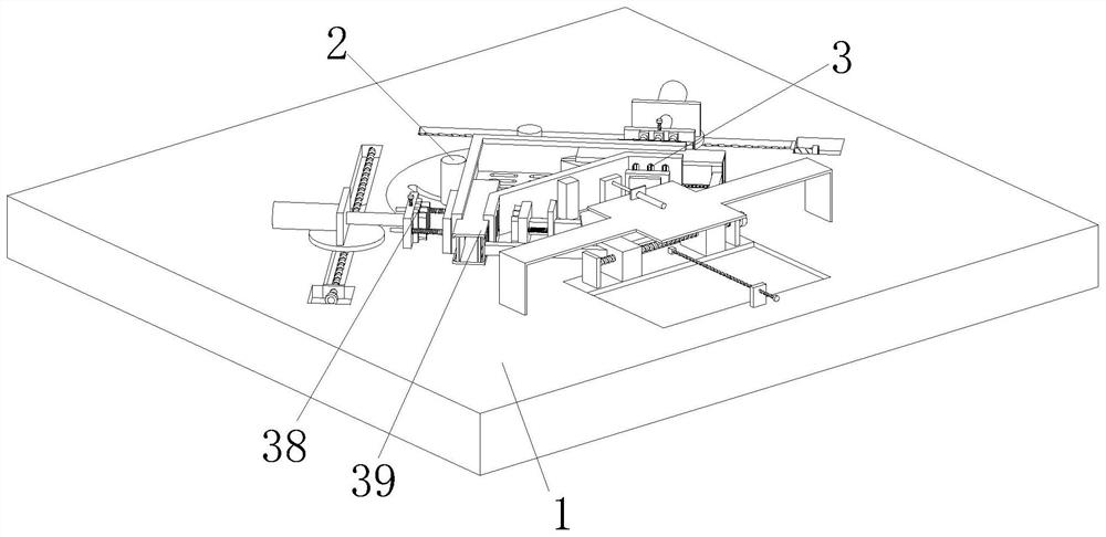
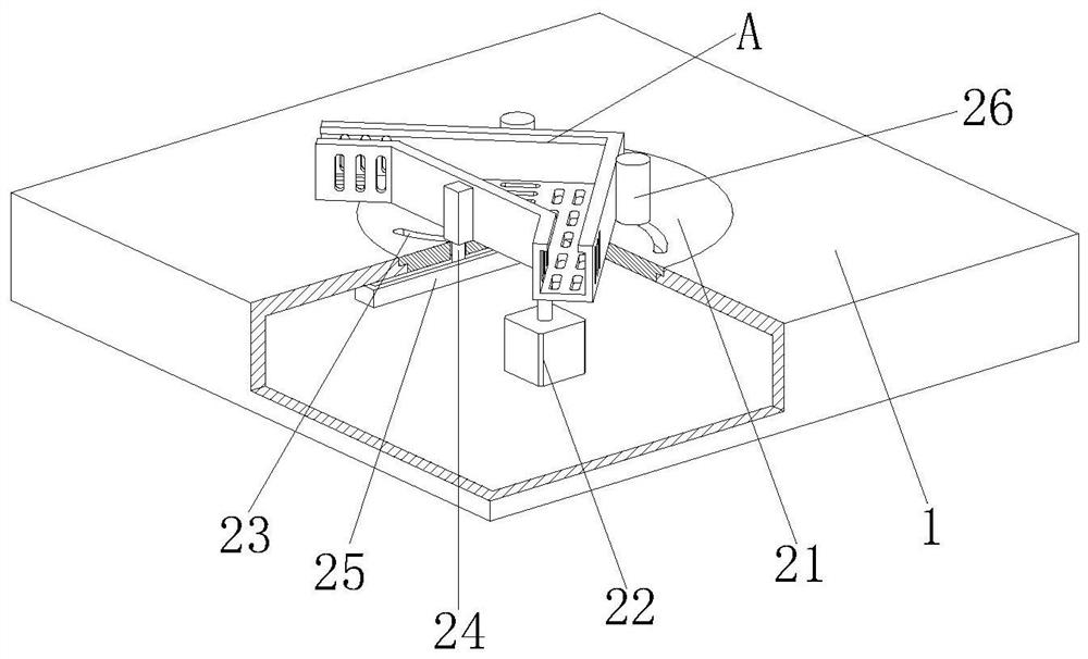
[0042] refer to Figure 1-14 , a forming process for making a power cable bridge, the forming process for making a power cable bridge adopts the following forming and processing equipment for making a power cable bridge, the equipment includes a placing operation frame 1, a fixing device 2 and a stamping device 3, the placing operation frame 1 is fixedly installed with a fixing device 2, and a punching device 3 is arranged on the placing operation frame 1; dur...


PUM


Abstract

The invention provides a power cable bridge manufacturing and forming processing technology, and relates to the technical field of power cable bridge processing. The power cable bridge manufacturing and forming processing technology comprises a placing operation frame, a fixing device and a stamping device, wherein the fixing device is fixedly installed on the placing operation frame, and the stamping device is arranged on the placing operation frame. The following problems can be solved: a, the stability of an existing power cable bridge is poor after the existing power cable bridge is clamped and fixed before the existing power cable bridge is punched, so that the power cable bridge is deviated after being subjected to external force during punching operation, and punching deviation is caused; and b, when the existing power cable bridge is processed, the punching position cannot be accurately positioned, the distances between holes tend to be different, the attractiveness of the power cable bridge is seriously influenced, and meanwhile, the existing equipment only can be used for punching the power cable bridge with the same size, so that the practicability of the equipment is poor.

Description

technical field [0001] The invention relates to the technical field of power cable bridge processing, and specifically proposes a manufacturing and forming process for power cable bridges. Background technique [0002] Power cable bridges are divided into trough-type, tray-type and ladder-type structures. Power cable bridges are composed of brackets, brackets and installation accessories. The bridges in buildings can be erected independently or attached to various buildings and pipes. On the corridor support, the power cable tray is conducive to the arrangement of messy cables, and at the same time will not affect the appearance of the external building. Due to the rapid development of economy and technology, the current buildings need to use more cables to transmit electric energy, so as to meet the production demand power supply , so power cable trays are widely used. [0003] The existing cables are mixed and stacked together, and they tend to heat up after power on. Whe...

Claims


Application Information

Patent Timeline
Patent Type & Authority Applications(China)
IPC IPC(8): H02G3/04B21D43/00B21D35/00
CPCH02G3/0406B21D35/001B21D35/002B21D43/003
Inventor 许和珊
Owner 深圳市熊猫眼通讯科技有限公司
Why Eureka
Try Eureka