Wireless charging coupling mechanism, wireless electric energy transmission system and method
A technology of wireless power transmission and coupling mechanism, which is applied to battery circuit devices, current collectors, electric vehicles, etc., and can solve the problems of low degree of freedom in wireless charging and high docking accuracy requirements at the receiving end
- Summary
- Abstract
- Description
- Claims
- Application Information
AI Technical Summary
Problems solved by technology
Method used
Image
Examples
Embodiment 1
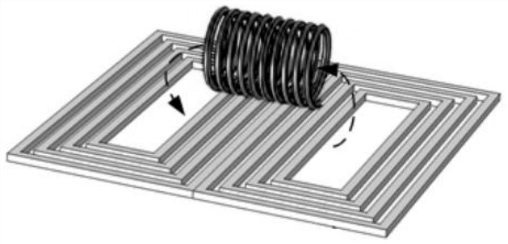
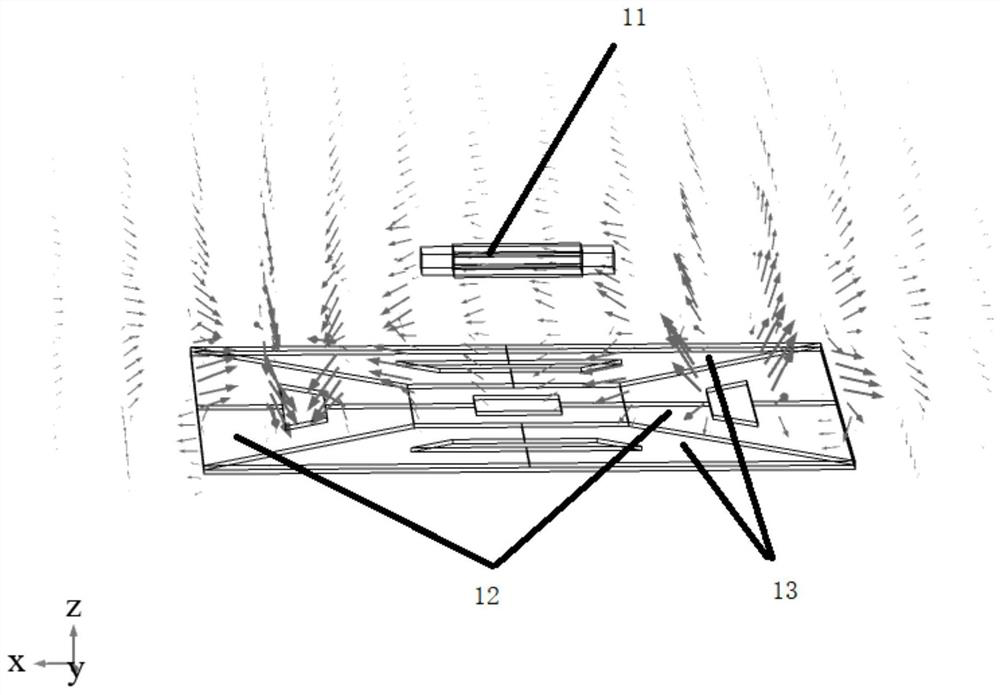
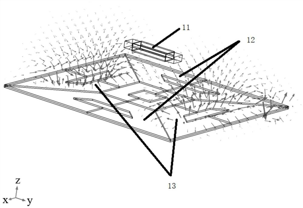
[0045] In order to solve the problems in the prior art that a single double D-type transmitting coil only generates a magnetic field in a horizontal direction, which requires high docking accuracy at the receiving end and low degree of freedom in wireless charging, this embodiment proposes a wireless charging coupling mechanism that can be applied Wireless charging scenarios for robots, cars, drones, etc., see Figure 2 to Figure 4 , a wireless charging coupling mechanism, comprising an energy transmitting device and an energy receiving device;
[0046] The energy transmitting device includes an energy transmitting coil; the energy receiving device includes an energy receiving coil;
[0047] The energy transmitting coil comprises a first coil group 12 and a second coil group 13; the first coil group 12 and the second coil group 13 respectively comprise two mutually axisymmetric coils; the symmetry axis of the first coil group 12 is the Y axis , the axis of symmetry of the sec...
Embodiment 2
[0057] In order to solve the problem in the prior art that a single double D-type transmitting coil only generates a magnetic field in a horizontal direction, which requires high docking precision at the receiving end and low degree of freedom in wireless charging, this embodiment proposes a wireless power transmission system, including the original Side power transmitting circuit, secondary side power receiving circuit;
[0058] The primary power transmission circuit includes sequentially connected DC power sources ( Figure 5 E in), full bridge inverter circuit ( Figure 5 The switching tube Q in 1 , Q 2 , Q 3 , Q 4 ), the primary side resonant compensation network ( Figure 5 The transmitter compensation coil L in t , the first compensation capacitor C t , the second compensation capacitor C p ), and the energy transmitting coil of the wireless charging coupling mechanism according to any one of the embodiments ( Figure 5 L in p1 and L p2 ); Figure 5 , also in...
PUM
 Abstract
Description
Claims
Application Information
 - R&D
- Intellectual Property
- Life Sciences
- Materials
- Tech Scout
- Unparalleled Data Quality
- Higher Quality Content
- 60% Fewer Hallucinations
Browse by: Latest US Patents, China's latest patents, Technical Efficacy Thesaurus, Application Domain, Technology Topic, Popular Technical Reports.
© 2025 PatSnap. All rights reserved.Legal|Privacy policy|Modern Slavery Act Transparency Statement|Sitemap|About US| Contact US: help@patsnap.com


