Injection mold rack angle ejector mechanism
A technology of inclined roof mechanism and injection mold, which is applied in the field of mold inclined roof mechanism, which can solve the problems of inconvenient maintenance, large space occupied by inclined roof and its components, and achieve high ejection efficiency, improved efficiency and good stability
- Summary
- Abstract
- Description
- Claims
- Application Information
AI Technical Summary
Problems solved by technology
Method used
Image

Examples
Embodiment 1
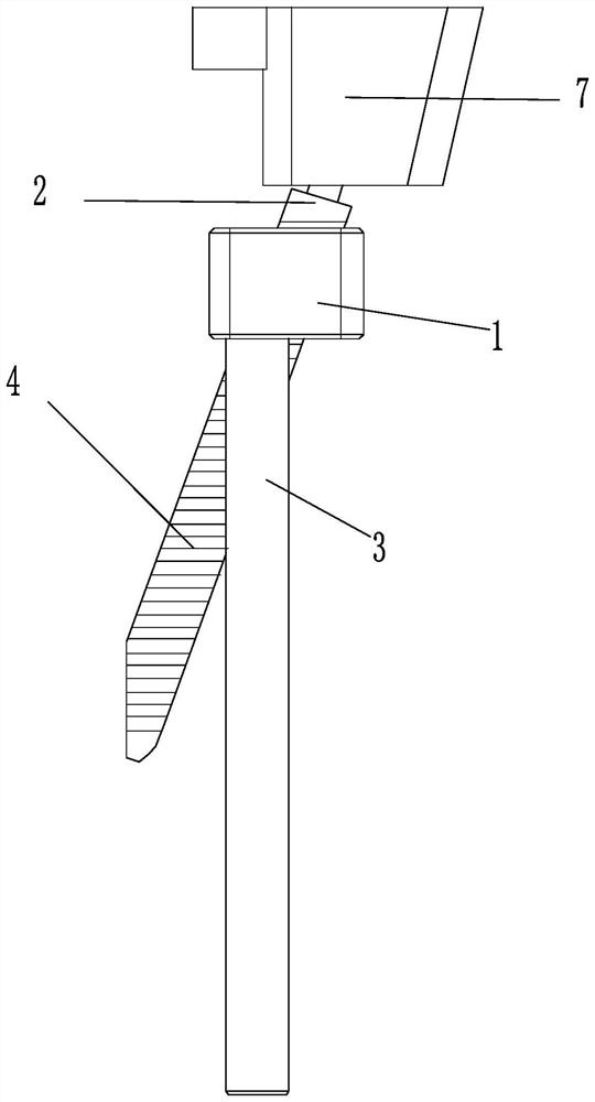
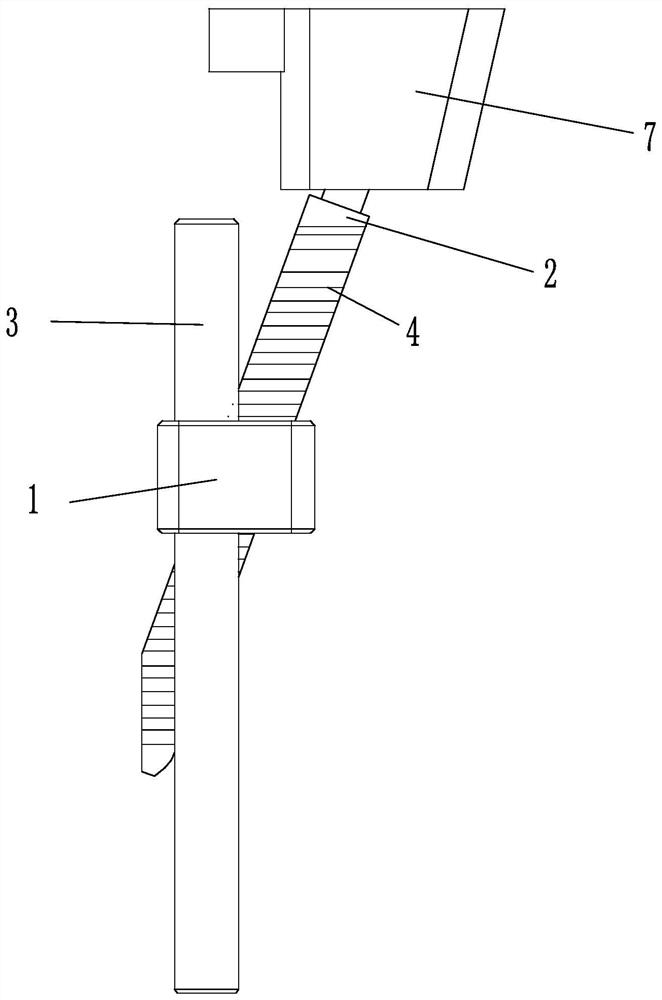
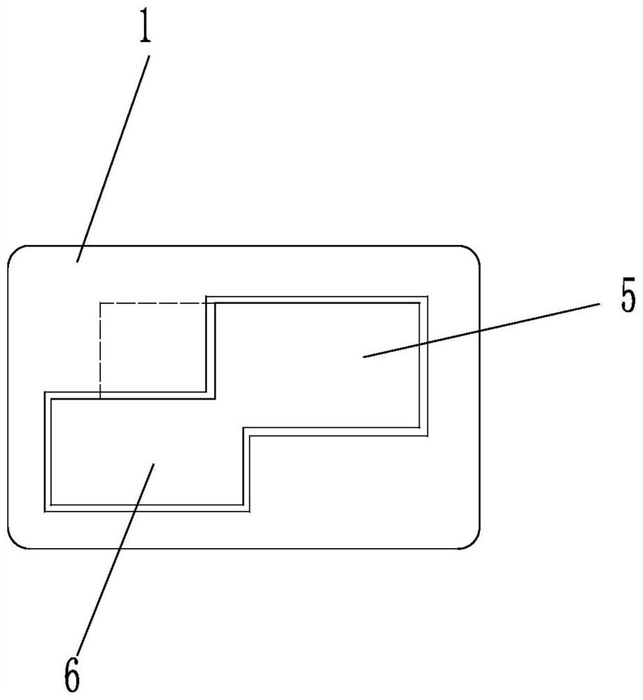
[0026] Such as figure 1 with figure 2 As shown, an injection mold rack inclined ejector mechanism is characterized in that it includes a fixed guide block 1, and also includes an inclined ejector rod 2 and a straight ejector rod 3 arranged in an intersecting state, and the inclined ejector rod 2 and the straight ejector rod 3 is provided with a matching pattern; the matching pattern adopts the tooth pattern 4 arranged perpendicular to the axis of the straight ejector rod 3 . The guide block 1 is provided with a sliding passage for matching the inclined ejector rod 2 and the straight ejector rod 3. The sliding passage includes a first passage 5 for matching the inclined ejector rod 2 and a second passage 6 for matching the straight ejector rod 3. The first passage 5 Intersecting and communicating with the second channel 6, the ends of the first channel 5 and the second channel 6 are respectively provided with transition arcs. from image 3 It can be seen that the cross-sect...
Embodiment 2
[0029] An injection mold rack inclined top mechanism, such as Figure 5 As shown, the difference between Embodiment 2 and Embodiment 1 lies in that the inclined ejector mechanism also includes a limit block 16 fixedly arranged relative to the guide block 1, the shape of the straight ejector rod 3 is cylindrical, and the inclined ejector rod 2 adopts a horizontal The cross-sectional shape is a rectangular strip structure. Adaptive design also needs to be carried out according to the shapes of the straight ejector rod 3 and the inclined ejector rod 2 in the guide block 1 . The matching pattern includes the thread on the upper section of the straight ejector rod 3 and the helical teeth 17 on the inclined ejector rod 2, the lower section of the straight ejector rod 3 is provided with a transmission thread 18, and the straight ejector rod 3 is provided with a connecting ring 19 that is convexly arranged, and the transmission thread 18 is arranged on the wall surface of connecting ...
Embodiment 3
[0032] An injection mold rack inclined top mechanism, such as Image 6 As shown, the difference between embodiment 3 and embodiment 2 is that there are two inclined ejector rods 2, and the upper and lower gaps 23 are set between the two inclined ejector rods 2, that is, there is a gap 23 between the two inclined ejector rods 2. The two inclined ejector rods 2 are arranged on the same side of the straight ejector rod 3, and the helical teeth 17 on the two inclined ejector rods 2 are arranged in parallel; The height of the helical teeth 17 of 2 is greater than the height of the helical teeth 17 of the slant ejector rod 2 on the upper side; the height difference of the helical teeth 17 on the two slant ejector rods 2 adopts 1 millimeter.
[0033] By arranging two inclined ejector rods 2 side by side in parallel, double locking can be formed, thereby improving the stability of cooperation between inclined ejector rods 2 and straight ejector rods 3; The cooperation between the eje...
PUM
 Abstract
Description
Claims
Application Information
 - Generate Ideas
- Intellectual Property
- Life Sciences
- Materials
- Tech Scout
- Unparalleled Data Quality
- Higher Quality Content
- 60% Fewer Hallucinations
Browse by: Latest US Patents, China's latest patents, Technical Efficacy Thesaurus, Application Domain, Technology Topic, Popular Technical Reports.
© 2025 PatSnap. All rights reserved.Legal|Privacy policy|Modern Slavery Act Transparency Statement|Sitemap|About US| Contact US: help@patsnap.com