Spray pipe for ejector, ejection unit and air ejector

A technology of ejectors and nozzles, applied in the field of wind tunnels, can solve the problems of difficult popularization and application of differential ejectors, energy loss of the ejected airflow, difficulty in design and processing, etc., and achieve easy installation and debugging, and low processing difficulty , overall good effect

Active Publication Date: 2021-03-09
CHINA ACAD OF AEROSPACE AERODYNAMICS
View PDF8 Cites 3 Cited by
  • Summary
  • Abstract
  • Description
  • Claims
  • Application Information

AI Technical Summary

Problems solved by technology

Due to its unique advantages, the multi-nozzle ejector has been more and more widely used. Most of the modern designed wind tunnels adopt the multi-nozzle ejector method, but this type of ejector, the ejector nozzle and the The structure of the ejected airflow channel is complex, and the design and processing are difficult, and multiple ejector nozzles are placed in the ejected airflow channel, which will cause a large energy loss to the ejected airflow
In addition, studies have shown that if the multi-nozzle ejector is improperly designed, the supersonic ejection airflow at the outlet of the multi-nozzle will collide with each other, which will aggravate the pressure loss
[0006] In addition to the above three ejectors, there is also a differential ejector in the prior art, which is a theoretical infinite multi-stage ejector. The application model of this ejector adopts the peripheral layout nozzle method to obtain a higher pressurization ratio, but the data show that with this ejector structure, only under a small diameter, the jet airflow in the ejector pipe can achieve effective mixing with the ejector airflow, and, in order to achieve For nozzle jets with different Ma numbers, dozens of nozzles need to be installed along the axial direction of the ejector pipe. The structure is complex and the processing is difficult. It is difficult for differential ejectors to be widely used in large-diameter wind tunnels.

Method used


Image

  • Spray pipe for ejector, ejection unit and air ejector
  • Spray pipe for ejector, ejection unit and air ejector
  • Spray pipe for ejector, ejection unit and air ejector

Examples


Embodiment 1

[0063] This embodiment provides a nozzle for the ejector, such as figure 2 , 3A with Figure 3B As shown in , the nozzle 3 is trumpet-shaped, including a large-diameter end and a small-diameter end, and at the large-diameter end of the nozzle 3, a connecting plate 14 is integrally formed along the circumference of the nozzle 3;

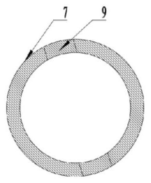
[0064] In the tube wall of the nozzle 3, an annular airflow chamber 17 is provided along the circumference of the nozzle 3, and the side of the annular airflow chamber 17 toward the small diameter end is provided with an annular opening, corresponding to the annular airflow chamber 17, and the opening The axial section includes a throat section 19 and an expansion section 18 connected in sequence. The throat section 19 is connected to the annular air flow chamber 17. The expansion section 18 is wedge-shaped, and its tip is connected to the throat section 19, and the other end extends to the end surface of the small diameter end. ;

[0065] On the ...

Embodiment 2

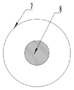
[0071] This embodiment provides an injection unit, such as Figure 3A with Figure 3B Shown, comprise the nozzle pipe 3 that is used for ejector in sleeve 4 and embodiment 1, one end of sleeve 4 is sleeved on nozzle pipe 3 by the small diameter end of nozzle pipe 3 and with the large diameter end of nozzle pipe 3 The connecting plate 14 is connected by a flange and a sealing gasket, the end surface of the small diameter end of the nozzle 3 is located in the sleeve 4, and the area distribution ratio of the two sides of the small diameter end of the nozzle 3 is F, F=1:1.

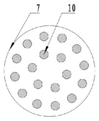
[0072] The ejector unit of this embodiment can make the ejected air flow sprayed into the sleeve from the small-diameter end of the nozzle pipe, the ejected air flow flows through the nozzle pipe and the air hole, and is ejected by the ejected air flow, and the ejected air flow contacts Large area, high mixing efficiency, and small airflow pressure loss.

Embodiment 3

[0074] This embodiment discloses an air injector, such as figure 2 As shown, it includes an intake pipe 1, a mixing chamber, and a diffuser pipe 5 connected in sequence, wherein the mixing chamber includes five injection units in Embodiment 2, and the five injection units are coaxially connected in series, and each injection unit The small-diameter ends of the nozzle pipes 3 are all facing the diffuser pipe 5, and the sleeve 4 of the upstream injection unit is connected to the connecting plate 14 of the large-diameter end of the nozzle pipe 3 of the downstream injection unit through a flange 6 and a sealing ring. ;

[0075] The front end of the intake pipe 1 is used to connect the supersonic diffuser, where the supersonic airflow has been decelerated and pressurized to a subsonic state, and the intake pipe accepts the subsonic airflow, which is the ejected airflow; the rear end of the intake pipe passes through the flange and The sealing ring is connected to the connecting p...


PUM


Abstract

The invention discloses a spray pipe for an ejector, an ejection unit and an air ejector. The spray pipe is horn-shaped and comprises a large-diameter end and a small-diameter end; an annular airflowstanding chamber is arranged in the pipe wall of the spray pipe in the circumferential direction of the spray pipe, an opening is formed in the side, facing the small-diameter end, of the annular airflow standing chamber, and the opening extends to the end face of the small-diameter end. A plurality of air inlets are formed in the large-diameter end of the spray pipe in the circumferential direction of the spray pipe, and each air inlet is connected to the annular airflow plenum chamber through an air inlet channel formed in the pipe wall of the spray pipe. According to the invention, the contact area of the injected airflow and the injected airflow can be increased, the pressure loss is reduced, and the mixing efficiency and the pressurization ratio are improved.

Description

technical field [0001] The invention belongs to the technical field of wind tunnels, and more specifically relates to a nozzle pipe for an ejector, an ejection unit and an air ejector. Background technique [0002] In the existing wind tunnel technology, there are mainly three types of ejector structures: central ejector, annular ejector and multi-nozzle ejector. [0003] Figure 1A It is the cross-sectional view of the mixing chamber inlet of the central ejector, and an ejecting nozzle 8 is installed in the pipeline center of the ejecting pipe 7, and the ejecting air flow is sprayed into the mixing chamber along the axial direction of the ejecting pipe 7 by the ejecting nozzle 8, The ejected airflow flows into the mixing chamber from around the ejector nozzle 8; this arrangement makes the ejected airflow near the wall of the ejector pipe 7 a low-speed ejected airflow, and the friction loss is small, but the airflow is unevenly mixed, and it is desired to achieve full mixing...

Claims


Application Information

Patent Timeline
Patent Type & Authority Applications(China)
IPC IPC(8): G01M9/04
CPCG01M9/04Y02E60/50Y02E10/72
Inventor 郭孝国马继魁陈培
Owner CHINA ACAD OF AEROSPACE AERODYNAMICS
Why Eureka
Try Eureka