Pass box
A technology for conveying boxes and items, applied in the field of conveying boxes
- Summary
- Abstract
- Description
- Claims
- Application Information
AI Technical Summary
Problems solved by technology
Method used
Image
Examples
no. 1 approach 》
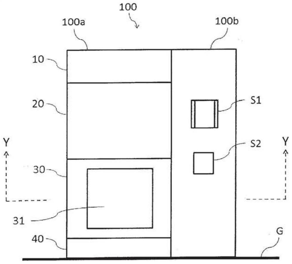
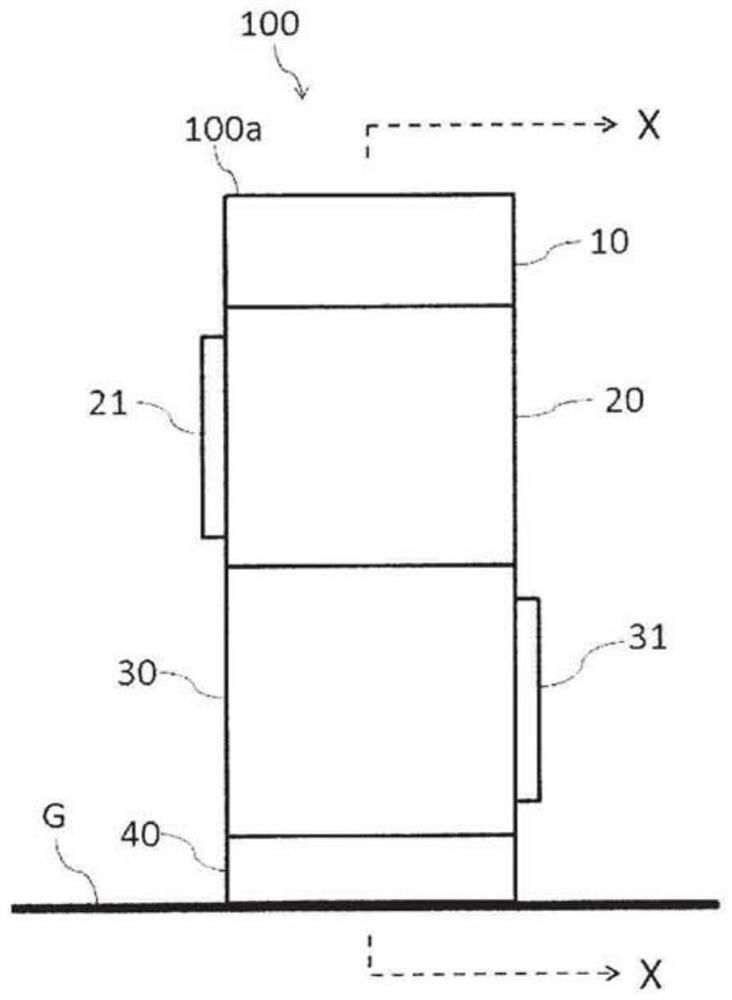
[0054] figure 1 is a front view of the transfer box according to the first embodiment, figure 2 is its left side view. exist figure 1 and figure 2 Among them, the transport box 100 according to the first embodiment is constituted by a transport box main body 100a placed on the floor surface G, and an electrical machine room 100b joined to the wall portion on the right side thereof. In this first embodiment, the rear wall of the transfer box 100 is connected to an isolator (not shown) that maintains an environment of level A under pharmaceutical GMP.
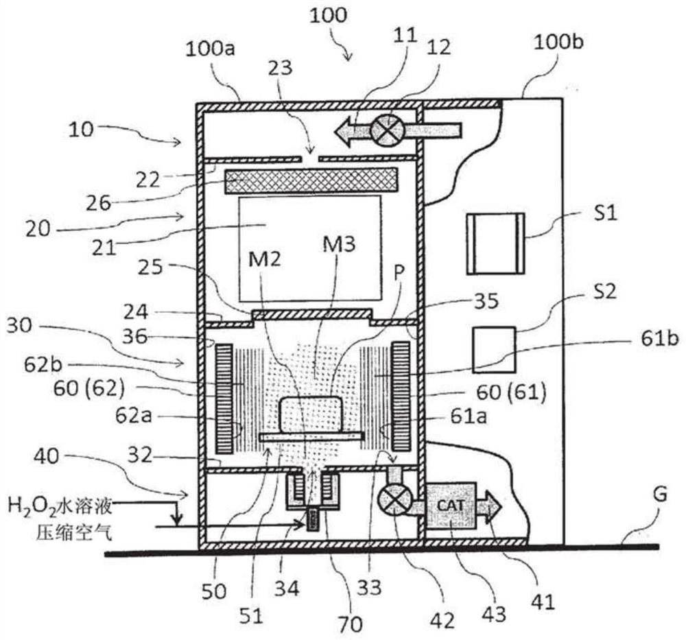
[0055] The transfer box main body 100a is composed of an upper machine room 10, a second room 20 (also referred to as an aeration room 20), a first room 30 (also called a decontamination room 30), and a lower machine room 40 from above. The upper machine room 10 has supply piping (described later) for supplying clean air to the aeration chamber 20 therein. The aeration chamber 20 is composed of a shell made of stainless st...
no. 2 approach 》
[0090] The decontamination agent control device of the above-mentioned first embodiment relates to the transfer box provided with two vibrating disks facing each other in the decontamination room. The delivery box for 2 vibrating plates. Figure 8 It is a top sectional view showing the outline of the inside of the first chamber (decontamination chamber) during decontamination of the transfer cassette according to the second embodiment. In addition, the front cross-sectional view showing the outline of the inside of the transfer box according to the second embodiment during decontamination and the front cross-sectional view showing the outline of the inside during aeration are the same as those of the above-mentioned first embodiment (see image 3 and Figure 7 ).
[0091] exist Figure 8 Among them, the transport box 200 according to the second embodiment is composed of a transport box main body 200a and an electrical machine room 200b joined to the wall portion on the righ...
no. 3 approach 》
[0103] In the above-mentioned first embodiment, the vibrating disk was not used for aeration, but in this third embodiment, a case where the vibrating disk is also used for aeration will be described. Figure 9 It is a front cross-sectional view showing the outline of the interior of the transfer box according to the third embodiment during aeration. In addition, the decontamination operation|movement of the conveyance box which concerns on this 3rd Embodiment can be performed similarly to the said 1st or 2nd Embodiment except the operation|movement of the vibration plate provided in an aeration chamber.
[0104] exist Figure 9 Among them, the transport box 300 according to the third embodiment is composed of a transport box main body 300a and an electrical machine room 300b joined to the wall portion on the right side thereof. The transfer box main body 300a is the same as the above-mentioned first embodiment, and consists of an upper mechanical chamber 310, a second chambe...
PUM
 Abstract
Description
Claims
Application Information
 - R&D
- Intellectual Property
- Life Sciences
- Materials
- Tech Scout
- Unparalleled Data Quality
- Higher Quality Content
- 60% Fewer Hallucinations
Browse by: Latest US Patents, China's latest patents, Technical Efficacy Thesaurus, Application Domain, Technology Topic, Popular Technical Reports.
© 2025 PatSnap. All rights reserved.Legal|Privacy policy|Modern Slavery Act Transparency Statement|Sitemap|About US| Contact US: help@patsnap.com


